20 |
Installation |
Loop M User Manual
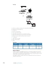
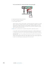
Device controlled from two relays (for example mast navigation light)
1D
1C
1B
1A
1E
1G
1H
4D
4C
4B
4A
4E
4F
4G
4H
A
B
C
A
Mast navigation light (white, 360 degrees)
B
Starboard navigation light (green)
C
Port navigation light (red)
The example shows three navigation lights connected between the DC negative bus and the
green connector pin 4A and 4F. Connector pin 4A is the output pin of relay R1 and pin 4F is
the output pin of relay R2, both relays can be individually controlled from the Loop system.
Diodes are connected to avoid conflicts between the relay outputs and the Mast navigation
light (can be powered by both relays).
¼
Note:
Only use diodes that can handle the total load of the connected equipment.
A 3-way bypass switch is connected to the black connector pin 1C and 1B. Connector pin 1C
is the bypass pin for relay R1 and connector pin 1B is the bypass pin for relay R2. The bypass
switch has three positions, mast navigation light bypassed, all navigation lights bypassed and
no bypass active.
When the bypass switch is closed (either bypassing relay R1 or R2), the corresponding relay
will be closed independent of the status in the software. If the bypass switch is closed, it is not
possible to turn the bypassed navigation light off from the software.


