background image

30 | 

Technical Specifications | 

Loop M User Manual

Technical Specifications

Egon+ board

!

Warning: 

IGNITION PROTECTED

 ONLY WHEN EQUIPPED WITH 

IGNITION PROTECTED FUSES AND COVER CLOSED.  

ANY REPLACEMENT FUSES MUST BE IGNITION PROTECTED

. COVER 

MUST BE CLOSED IN EVERY OPERATIONAL CONDITION!

Environmental

Operating temperature

-40°C to 85°C

Storage temperature

-40°C to 125°C

Mechanical shock

SAE J2030 (RDEC2002), Section 6.16

Bombardment test

24 hour of dust, sand and gravel

Salt fog

96 hour period of salt fog per ASTM B117-94

Protection class

IP 66

Vibration

SAE J1455 (R2006), Section 4.10.4.2

Chemical resistance

Break fluid, AT fluid, antifreeze fluid, windshield 
wash fluid, PS fluid and oil.

Electrical

Power supply voltage

12 V DC (8-16 V DC)

Dielectric voltage withstanding

80 V DC

Current consumption

1.5 mA battery quiescent current

Total current limit

200 A

Total current limit per connector

100 A

Overload

135%

Temperature rise

60°C

Insulation resistance

10 MOhm

Max load

Fuse channels 30 A at 12 V DC

Relay and fuse channels 20 A (resistive load)/16 A (inductive, motor, 

pump load) at 12 V DC 

Maximum board load 

200 A

Power connector

2x M8 input studs, each rated at 100 A 
maximum

Power wire size

Calculated based on total board consumption

Output wire size

1.31 mm2 - 5.26 mm2 (#10-16 AWG)

Fuses

Mini blade fuse

Relays

280 footprint, 4 pin relay

Abnormal conditions

Revers polarity protection

- 24 V DC, SAE J1455 (RJUN2006) - duration of 5 
minutes

Short circuit protection

Short to ground 5 minutes, ER455 (R2008) Section 5.10.4

Short to 16 V DC 5 minutes, ER455 (R2008) Section 5.10.4

Power up operation

Ramp battery voltage from 0 to minimum 
operating voltage ad 1 V/ms, EP455 (R2008) 
Section 5.10.7

5

Summary of Contents for Naviop Loop M

Page 1: ...ENGLISH LoopM User Manual www bandg com www simrad yachting com www lowrance com...

Page 2: ......

Page 3: ...ers About this manual This manual is a reference guide for installing and operating the Loop system Some features may not be activated or available for screenshots in the manual As a result screenshot...

Page 4: ...em example 6 Get the system up and running 7 Installation 7 Mounting 8 Wiring 21 Configuration 21 Requirements 21 Configuring 24 How to install the Loop M software 26 Operation 26 Start up 26 The cont...

Page 5: ...system is switched off or there are communication errors between the system and the equipment it monitors all bypassed relays can be controlled manually Note For specific information on the operation...

Page 6: ...ystem A B E F C D 12 V DC 12 V A MFD B Ethernet network C OP Box Loop M M D Naviop CAN network E Egon board F Controlled and or monitored equipment Get the system up and running To get the system up a...

Page 7: ...es to the intended mounting location Note The enclosure should be dry and well ventilated In small enclosures it may be required to fit forced cooling Warning Inadequate ventilation and subsequent ove...

Page 8: ...hem secure Solder crimp and insulate all wiring connections if extending or shortening the cables Use suitable crimp connectors or solder and heat shrink when extending cables Keep joins as high as po...

Page 9: ...bone The terminator can be a terminator plug or a unit with built in terminator A A A A C C D B B B B E F A NMEA 2000 device B Drop cable C Terminator D Power supply E Backbone F OP Box Loop M M NMEA...

Page 10: ...2000 drop cable K NMEA 2000 backbone L MFD System IDs System Egon boards Controlable outputs Monitored power outputs Drop cable ID Loop M 1 8 8 CAN ID 1 Loop M 2 16 16 CAN ID 1 CAN ID 2 Ethernet netwo...

Page 11: ...op CAN network G LED indicators LED indicators A B C 0 LED Status Description A Power Off CPU error no power supply On Operating mode operation completed successfully Flashing slow Error during last o...

Page 12: ...used for software updates and system configuration Refer to Configuration on page 21 Naviop CAN The OP Box Loop M M is equipped with two Micro C CAN connectors The connector labeled CAN 0 shall be use...

Page 13: ...AND COVER CLOSED ANY REPLACEMENT FUSES MUST BE IGNITION PROTECTED COVER MUST BE CLOSED IN EVERY OPERATIONAL CONDITION Warning Always use a fuse that is appropriate for the connected load The supplied...

Page 14: ...0 2C F11 2B F12 2A F15 2G F16 2H E F CAN OUT 1 OUT 2 OUT 3 OUT 4 OUT 5 OUT 6 OUT 7 OUT 8 OUT 9 OUT 10 OUT 11 OUT 12 OUT 13 OUT 14 OUT 15 OUT 16 A Main power input B Fuses C Relays D Override pins for...

Page 15: ...D of the cable Egon board D 12 V DC power supply E Naviop CAN backbone F Fuse 2A Egon board power input Warning The Egon board is equipped with 12 V DC rated relays The input voltage should match the...

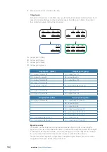
Page 16: ...fuse F14 1G bypass for relay R6 2G output fuse F15 1H bypass for relay R8 2H output fuse F16 Output port 3 blue Output port 4 green 3A bypass for relay R4 4A output relay R1 fuse F1 4B output fuse F8...

Page 17: ...cables to the wire terminals Always use a fuse that is appropriate for the connected load The fuses supplied may have to be replaced to match the outputs connected load B C D E F A A Wire B Wire seal...

Page 18: ...ch is closed the relay will be closed independent of the status in the software If the bypass switch is closed it is not possible to turn the bilge pump supply off from the software The bypass switch...

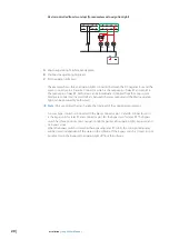
Page 19: ...nnecting an indicator light to a relay output 1D 1C 1B 1A 1E 1G 1H 2C 2B 2A 2E 2G 2H 1D 1C 1B 1A 1E 1G 1H 2C 2B 2A 2E 2G 2H The example shows a load light bulb connected between the DC negative bus an...

Page 20: ...onnected to avoid conflicts between the relay outputs and the Mast navigation light can be powered by both relays Note Only use diodes that can handle the total load of the connected equipment A 3 way...

Page 21: ...boat builder and or installing dealer Safe storage and retrieval of this unique file is the responsibility of the boat builder and or installing dealer It is important to make a copy of this configur...

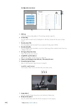
Page 22: ...archive containing all files needed to install the Loop software in the boat E Set App configurator help Opens the Set App user manual F Loop M M specific options Refer to Loop M M specific options o...

Page 23: ...ll not be used for Loop M systems B App name Specify a name for the configuration The name is used to identify the configuration to be used by the MFD Edit channels output settings D B C F H G A E A E...

Page 24: ...controlled by an external switch For connection examples refer to Connection examples on page 17 How to install the Loop M software 1 Select the Set App to open the configurator 2 Open the Settings di...

Page 25: ...d be automatically enabled when the MFD is configured and the Loop system is correctly installed If it does not show up you can manually activate the feature from the advanced system settings A The ap...

Page 26: ...ed from the MFD s control bar or from the Naviop application Refer to the MFD documentation for details about how to operate the MFD The control bar interface Buttons The button indicates the status o...

Page 27: ...long as the fuse is ok A Communication error If a communication error occurs all button and fuses status indicators will turn red The Naviop application interface When a Loop system is connected to yo...

Page 28: ...closed Override yellow The relay control is bypassed by an external switch or the equipment is powered from another source not via the relay Error red The fuse and or relay is broken For more informa...

Page 29: ...nostic pages A Communication error If a communication error occurs a text will be shown on the relevant diagnostic page instead of an overview of the fuses and relays layout illustration Egon board be...

Page 30: ...ric voltage withstanding 80 V DC Current consumption 1 5 mA battery quiescent current Total current limit 200 A Total current limit per connector 100 A Overload 135 Temperature rise 60 C Insulation re...

Page 31: ...2 optical isolation 1kV SD Card Expansion LED indicators 5 Power Ethernet status Ratings Power supply 9 to 32 V DC Current consumption 0 15A max at 24 V DC LEN 0 Input protection Electronic Battery Y...

Page 32: ......

Page 33: ...988 12394 003 www bandg com www simrad yachting com www lowrance com...

Reviews: