10
419050/B
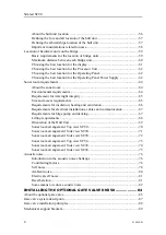
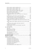
Checking the transducer lower and hoist functionality ........................................341
Testing the Operating Panel to verify basic functionality ....................................345
Testing the user interface to verify basic functionality ........................................349
Verifying SC90 operation by means of the BITE functionality ...........................351
Measuring the Echo level in
mode..........................................................355
Measuring the output voltages from the Power Supply Unit ...............................357
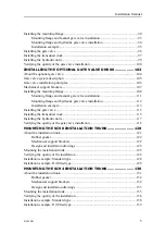
Making a noise/speed curve to determine vessel noise ........................................358
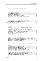
Verifying the communication with a navigation system (GPS) ...........................363
Verifying the communication with speed log.......................................................365
Verifying the communication with the course gyro .............................................367
Verifying the communication with the motion reference unit (MRU) .................368
Verifying the alignment of the SC90 presentation (SC90)...................................372
Verifying the alignment of the SC90 presentation (SC94)...................................374
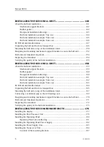
Verifying the installation parameters for the global positioning system (GPS)
Verifying the installation parameters for the transducer ......................................377
Verifying the physical dimensions of the ship......................................................379
Adjusting the offset angle between the motion sensor and the direction of the
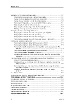
Creating a backup with the SC90 configuration and software installation....................383
Restoring a Processor Unit image from a USB flash drive using the Acronis
Creating a bootable USB flash drive using the Acronis True Image
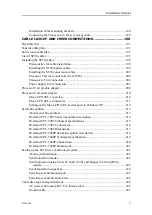
TECHNICAL SPECIFICATIONS.............................................. 391
Introduction to technical specifications .........................................................................392
Performance specifications ............................................................................................392
Power requirements .......................................................................................................395
Weight and outline dimensions ......................................................................................397
Environmental requirements..........................................................................................399
Compass safe distance ...................................................................................................400
Minimum display requirements .....................................................................................401
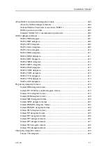
DATAGRAM FORMATS .......................................................... 403
Simrad SC90
Summary of Contents for SC90
Page 2: ......
Page 16: ...14 419050 B Simrad SC90 ...
Page 219: ...419050 B 217 Øverland UPC 3005 Dimensions Cable layout and interconnections ...
Page 223: ...419050 B 221 Øverland UPC 5000P Dimensions Cable layout and interconnections ...
Page 438: ...436 419050 B 427177 Transducer dock dimensions page 494 Simrad SC90 Installation Manual ...
Page 441: ...419050 B 439 Drawing file ...
Page 442: ...440 419050 B Simrad SC90 Installation Manual ...
Page 445: ...419050 B 443 Drawing file ...
Page 452: ...450 419050 B Simrad SC90 Installation Manual ...
Page 455: ...419050 B 453 Drawing file ...
Page 458: ...456 419050 B Simrad SC90 Installation Manual ...
Page 463: ...419050 B 461 Drawing file ...
Page 468: ...466 419050 B Simrad SC90 Installation Manual ...
Page 469: ...419050 B 467 Related topics Installing the optional gate valve DN350 page 84 Drawing file ...
Page 471: ...419050 B 469 Drawing file ...
Page 473: ...419050 B 471 214043 Gate valve installation DN350 Drawing file ...
Page 475: ...419050 B 473 422915 Gate valve installation DN350 Drawing file ...
Page 477: ...419050 B 475 083045 Gate valve installation DN500 Drawing file ...
Page 479: ...419050 B 477 33414 Gate valve dimensions DN350 Drawing file ...
Page 480: ...478 419050 B Simrad SC90 Installation Manual ...
Page 481: ...419050 B 479 Related topics Installing the optional gate valve DN350 page 84 Drawing file ...
Page 482: ...480 419050 B 33473 Gate valve dimensions DN350 Simrad SC90 Installation Manual ...
Page 483: ...419050 B 481 Related topics Installing the optional gate valve DN350 page 84 Drawing file ...
Page 484: ...482 419050 B 33498 Gate valve dimensions DN500 Simrad SC90 Installation Manual ...
Page 485: ...419050 B 483 Drawing file ...
Page 487: ...419050 B 485 37357 Gate valve dimensions DN500 Drawing file ...
Page 488: ...486 419050 B Simrad SC90 Installation Manual ...
Page 489: ...419050 B 487 Related topics Installing the optional gate valve DN500 page 103 Drawing file ...
Page 491: ...419050 B 489 Drawing file ...
Page 494: ...492 419050 B Simrad SC90 Installation Manual ...
Page 495: ...419050 B 493 Related topics Installing the optional gate valve DN350 page 84 Drawing file ...
Page 497: ...419050 B 495 Drawing file ...
Page 542: ... 2018Kongsberg Maritime ISBN xxx ...
Page 543: ......
Page 544: ...Simrad SC90 Fish finding sonar Installation Manual ...

