419050/B
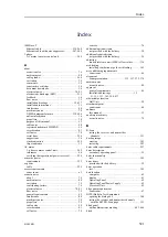
527
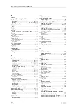
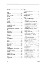
choose the best location for the Operating
Panel ..................................................... 62
choose the best location for the Operating Panel
Power Supply ........................................... 62
choose the best location for the Processor
Unit....................................................... 62
clean a electromechanical unit ....................... 510
clean a hull unit ........................................ 510
clean a mechanical unit ............................... 510
clean an electronic cabinet............................ 508
clean an electronic unit................................ 508
connect transducer to the transceiver................ 305
connect transducer to the Transceiver Unit......... 305
create a backup image on a USB flash drive ........ 383
create a bootable USB flash drive ................... 386
define athwartships location of the Hull Unit ........ 58
define fore and aft location of the Hull Unit ......... 57
define sound speed value ............................. 319
define sound velocity value........................... 319
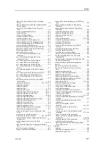
do a environmental inspection of the
transceiver ............................................. 279
do a environmental inspection of the
Transceiver Unit ...................................... 279
do a visual inspection of the computer.............. 270
do a visual inspection of the display ................ 268
do a visual inspection of the hull unit ............... 276
do a visual inspection of the Operating
Panel ................................................... 271
do a visual inspection of the Power Supply
Unit..................................................... 274
do a visual inspection of the Processor Unit ........ 270
do a visual inspection of the transceiver ............ 272
do a visual inspection of the Transceiver
Unit..................................................... 272
fine tune the motion reference unit (MRU)
offset values ........................................... 336
inspect the transducer ..................... 154, 172, 277
install the computer.................................... 178
install the display ...................................... 177
install the Enix ......................................... 178
install the gate valve............................... 96, 113
install the Gate Valve Control Unit.............. 99, 117
install the Hydraulic Power Pack ................ 99, 117
install the mounting flange ....................... 90, 108
install the Operating Panel............................ 180
install the Operating Panel Power Supply .......... 182
install the Power Supply Unit ........................ 183
install the Processor Unit ............................. 178
install the Transceiver Unit ........................... 184
install the transducer dock ........................ 97, 115
install ventilation pipe for air bleeding ............. 169
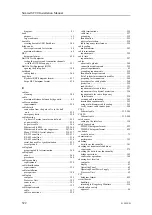
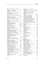
lift units and transportation boxes ................... 499
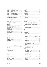
make a noise/speed curve to determine vessel
noise.................................................... 358
measure noise at different speeds.................... 358
measure noise in passive mode .......... 301, 303, 355
measure the DC output voltages from the Power
Supply Unit ........................................... 357
mount support brackets on the Hull
Unit............................................... 152, 170
open the BITE (Built-In Test Equipment) dialog
box ..................................................... 388
pack for storage or shipment ......................... 507
prepare a cable for termination....................... 260
restore from a backup image on a USB flash
drive .................................................... 385
return electronic modules to Kongsberg
Maritime ............................................... 514
return printed circuit boards to Kongsberg
Maritime ............................................... 514
secure and terminate a cable.......................... 262
select synchronization mode ......................... 226
select synchronization port ........................... 225
set to work .............................................. 266
set up synchronization........................... 225–226
set up the catch sensor interface ..................... 330
set up the GPS interface............................... 328
set up the gyro interface............................... 324
set up the motion reference unit (MRU)
interface................................................ 333
set up the navigation sensor interface ............... 328
set up the speed log interface......................... 326
set up the trawl system interface..................... 331
start the Processor Unit for the first time ........... 299
test the Operating Panel to verify basic
functionality........................................... 345
test the receiver and transmitter channels with
the BITE B-Scan page ............................... 351
transport Kongsberg Maritime equipment.......... 498
turn on ................................................... 311
turn on the system for the first time ................. 307
turn on the Transceiver Unit for the first
time..................................................... 300
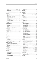
unpack a mechanical unit ............................. 504
unpack an electromechanical unit ................... 505
unpack an electronic unit ............................. 505
unpack and handle electronic modules.............. 512
unpack and handle printed circuit boards........... 512
unpack standard parts and units...................... 503
unpack the hull unit.............................. 148, 165
use multi-diameter cable sealing..................... 263
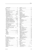
verify basic functionality ............................. 349
verify correct cable connections ..................... 280
verify ship dimensions ................................ 379
verify that operational power is correct............. 298
verify the communication with the motion
reference unit (MRU) ................................ 368
verify the GPS interface ........................ 363, 367
verify the installation parameters for the GPS
antenna................................................. 376
verify the installation parameters for the
transducer.............................................. 377
verify the navigation sensor
interface.......................................... 363, 367
verify the quality of the hull unit
installation....................................... 155, 173
verify the quality of the installation trunk
mounting ........................................ 126, 136
verify the quality of the mounting
flange, gate valve and transducer dock
installation....................................... 100, 118
verify the quality of the sonar room ........... 155, 173
verify the speed log interface......................... 365
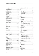
visual inspection of units and transportation
boxes after arrival .................................... 500
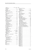
cleaning ................................................. 510
connecting to emergency hoist ....................... 250
connecting to gate valve .............................. 252
Index
Summary of Contents for SC90
Page 2: ......
Page 16: ...14 419050 B Simrad SC90 ...
Page 219: ...419050 B 217 Øverland UPC 3005 Dimensions Cable layout and interconnections ...
Page 223: ...419050 B 221 Øverland UPC 5000P Dimensions Cable layout and interconnections ...
Page 438: ...436 419050 B 427177 Transducer dock dimensions page 494 Simrad SC90 Installation Manual ...
Page 441: ...419050 B 439 Drawing file ...
Page 442: ...440 419050 B Simrad SC90 Installation Manual ...
Page 445: ...419050 B 443 Drawing file ...
Page 452: ...450 419050 B Simrad SC90 Installation Manual ...
Page 455: ...419050 B 453 Drawing file ...
Page 458: ...456 419050 B Simrad SC90 Installation Manual ...
Page 463: ...419050 B 461 Drawing file ...
Page 468: ...466 419050 B Simrad SC90 Installation Manual ...
Page 469: ...419050 B 467 Related topics Installing the optional gate valve DN350 page 84 Drawing file ...
Page 471: ...419050 B 469 Drawing file ...
Page 473: ...419050 B 471 214043 Gate valve installation DN350 Drawing file ...
Page 475: ...419050 B 473 422915 Gate valve installation DN350 Drawing file ...
Page 477: ...419050 B 475 083045 Gate valve installation DN500 Drawing file ...
Page 479: ...419050 B 477 33414 Gate valve dimensions DN350 Drawing file ...
Page 480: ...478 419050 B Simrad SC90 Installation Manual ...
Page 481: ...419050 B 479 Related topics Installing the optional gate valve DN350 page 84 Drawing file ...
Page 482: ...480 419050 B 33473 Gate valve dimensions DN350 Simrad SC90 Installation Manual ...
Page 483: ...419050 B 481 Related topics Installing the optional gate valve DN350 page 84 Drawing file ...
Page 484: ...482 419050 B 33498 Gate valve dimensions DN500 Simrad SC90 Installation Manual ...
Page 485: ...419050 B 483 Drawing file ...
Page 487: ...419050 B 485 37357 Gate valve dimensions DN500 Drawing file ...
Page 488: ...486 419050 B Simrad SC90 Installation Manual ...
Page 489: ...419050 B 487 Related topics Installing the optional gate valve DN500 page 103 Drawing file ...
Page 491: ...419050 B 489 Drawing file ...
Page 494: ...492 419050 B Simrad SC90 Installation Manual ...
Page 495: ...419050 B 493 Related topics Installing the optional gate valve DN350 page 84 Drawing file ...
Page 497: ...419050 B 495 Drawing file ...
Page 542: ... 2018Kongsberg Maritime ISBN xxx ...
Page 543: ......
Page 544: ...Simrad SC90 Fish finding sonar Installation Manual ...


