419050/B
537
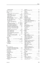
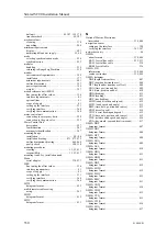
support brackets
hull unit ................................. 89, 107, 152, 170
transducer dock .................................... 89, 107
support information......................................... 47
switch
on ........................................................ 311
important reminder ...................................... 18
about ..................................................... 222
cables using RS-232 serial line ...................... 235
selecting synchronization mode...................... 226
selecting synchronization port ....................... 225
setting up.......................................... 225–226
using Clear To Send (CTS) and Request To
Send (RTS) signals ................................... 224
using RS-232 serial line......................... 241, 243
description .............................................. 223
selecting ................................................. 226
selecting ................................................. 225
description ................................................ 19
diagram.................................................... 21
key features ............................................... 20
turning on the system for the first time ............. 307
description .............................................. 191
list ........................................................ 195
system description
gate valve ........................................... 87, 105
important reminder ...................................... 18
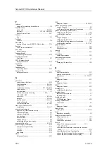
T
this manual................................................ 15
datagram format........................................ 425
specifications ........................................... 392
display ................................................... 401
uninterruptible power supply...................... 35, 44
Øverland UPC-3005 Serial line splitter............. 215
Øverland UPC-5000P Serial line splitter ........... 219
sonar room ................................................ 67
MTW datagram format................................ 422
requirements ............................................ 399
cable ..................................................... 262
preparing cable ......................................... 260
cable requirements..................................... 259
basic functionality ..................................... 349
basic operation ......................................... 349
Operating Panel ........................................ 345
hoist/lower functionality .............................. 341
datagram format........................................ 425
purpose .................................................... 15
target audience ........................................... 15
supply power ............................................. 44
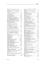
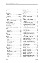
top view
sonar room arrangement ............... 70, 73, 144, 161
cable plan ............................................... 192
datagram format........................................ 426
datagram format........................................ 426
datagram format........................................ 427
TPP datagram format.................................. 426
connecting transducer ................................. 305
environmental inspection ............................. 279
environmental requirements.......................... 399
outline dimensions..................................... 397
power requirements.................................... 395
visual inspection ....................................... 272
weight ................................................... 397
connecting transducer ................................. 305
connectors............................................... 206
environmental inspection ............................. 279
environmental requirements.......................... 399
installation .............................................. 184
introduction ............................................... 24
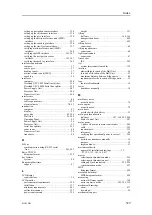
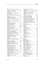
outline dimensions..................................... 397
outline dimensions drawing .......................... 442
overview .................................................. 24
power requirements.................................... 395
purpose .................................................... 24
turning on for the first time ........................... 300
visual inspection ....................................... 272
weight ................................................... 397
checking the hoist/lower functionality .............. 341
connecting to the transceiver ......................... 305
connecting to the Transceiver Unit .................. 305
hoist/lower manually .................................... 18
introduction ............................................... 29
overview .................................................. 29
purpose .................................................... 29
verify installation parameters for antenna .......... 377
visual inspection ........................... 154, 172, 277
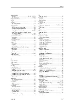
transducer dock
mechanical support ................................ 89, 107
mounting ............................................ 97, 115
outline dimensions drawing .............. 488, 491, 494
quality check ..................................... 100, 118
support brackets.................................... 89, 107
transducer handling
important rules ................................ 19, 29, 511
of delicate and fragile equipment .................... 498
TPT datagram format.................................. 427
Index
Summary of Contents for SC90
Page 2: ......
Page 16: ...14 419050 B Simrad SC90 ...
Page 219: ...419050 B 217 Øverland UPC 3005 Dimensions Cable layout and interconnections ...
Page 223: ...419050 B 221 Øverland UPC 5000P Dimensions Cable layout and interconnections ...
Page 438: ...436 419050 B 427177 Transducer dock dimensions page 494 Simrad SC90 Installation Manual ...
Page 441: ...419050 B 439 Drawing file ...
Page 442: ...440 419050 B Simrad SC90 Installation Manual ...
Page 445: ...419050 B 443 Drawing file ...
Page 452: ...450 419050 B Simrad SC90 Installation Manual ...
Page 455: ...419050 B 453 Drawing file ...
Page 458: ...456 419050 B Simrad SC90 Installation Manual ...
Page 463: ...419050 B 461 Drawing file ...
Page 468: ...466 419050 B Simrad SC90 Installation Manual ...
Page 469: ...419050 B 467 Related topics Installing the optional gate valve DN350 page 84 Drawing file ...
Page 471: ...419050 B 469 Drawing file ...
Page 473: ...419050 B 471 214043 Gate valve installation DN350 Drawing file ...
Page 475: ...419050 B 473 422915 Gate valve installation DN350 Drawing file ...
Page 477: ...419050 B 475 083045 Gate valve installation DN500 Drawing file ...
Page 479: ...419050 B 477 33414 Gate valve dimensions DN350 Drawing file ...
Page 480: ...478 419050 B Simrad SC90 Installation Manual ...
Page 481: ...419050 B 479 Related topics Installing the optional gate valve DN350 page 84 Drawing file ...
Page 482: ...480 419050 B 33473 Gate valve dimensions DN350 Simrad SC90 Installation Manual ...
Page 483: ...419050 B 481 Related topics Installing the optional gate valve DN350 page 84 Drawing file ...
Page 484: ...482 419050 B 33498 Gate valve dimensions DN500 Simrad SC90 Installation Manual ...
Page 485: ...419050 B 483 Drawing file ...
Page 487: ...419050 B 485 37357 Gate valve dimensions DN500 Drawing file ...
Page 488: ...486 419050 B Simrad SC90 Installation Manual ...
Page 489: ...419050 B 487 Related topics Installing the optional gate valve DN500 page 103 Drawing file ...
Page 491: ...419050 B 489 Drawing file ...
Page 494: ...492 419050 B Simrad SC90 Installation Manual ...
Page 495: ...419050 B 493 Related topics Installing the optional gate valve DN350 page 84 Drawing file ...
Page 497: ...419050 B 495 Drawing file ...
Page 542: ... 2018Kongsberg Maritime ISBN xxx ...
Page 543: ......
Page 544: ...Simrad SC90 Fish finding sonar Installation Manual ...


