136
419050/B
Verifying the quality of the installation
Once the installation trunk and blister have been installed, a quality inspection must take
place. The purpose of the inspection is to makes sure that the installation trunk has been
installed correctly, and that the hull unit can be mounted on top of it.
Prerequisites
Neither tools nor instruments are required.
Context
The installation trunk must be mounted so that it remains vertical during normal
operating conditions.
The top mating surface of the installation trunk must be protected with a wooden cover
at all times until the hull unit is installed. It is very important that this surface is clean
and undamaged, because it must be watertight after the hull unit has been installed
on top of the installation trunk.
Objects protruding from the hull will generate turbulence and flow noise. This will
reduce the SC90 performance. Protruding objects may be zinc anodes, transducers or
even the vessel's keel. Holes and pipe outlets are also important noise sources, as well as
rough surfaces caused by bad welding. Even traces of sealing compound, sharp edges,
bolts or empty bolt holes will create noise.
Procedure
1
Write down the key measurements.
This is for future reference.
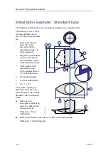
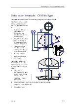
• Horizontal distance from the keel to the centre of the installation trunk
• Height from the bottom of keel to the top of the installation trunk
• Total height of the installation trunk (with optional blister)
2
Do a close visual inspection of the physical properties of the installation trunk and
the way it has been installed.
Refer to the applicable requirements.
a
Make sure that the upper surface of the installation trunk is level, undamaged
and clean.
b
Make sure that the installation trunk has been properly stiffened in both the
fore-and-aft and athwartship directions by means of strengthening knee plates.
c
Make sure that the installation trunk has been properly braced to the hull
plating and the surrounding hull frames.
3
Do a close visual inspection of the blister and the hull plating close to the
installation trunk.
Check for any kind of objects that may cause noise.
Simrad SC90 Installation Manual
Summary of Contents for SC90
Page 2: ......
Page 16: ...14 419050 B Simrad SC90 ...
Page 219: ...419050 B 217 Øverland UPC 3005 Dimensions Cable layout and interconnections ...
Page 223: ...419050 B 221 Øverland UPC 5000P Dimensions Cable layout and interconnections ...
Page 438: ...436 419050 B 427177 Transducer dock dimensions page 494 Simrad SC90 Installation Manual ...
Page 441: ...419050 B 439 Drawing file ...
Page 442: ...440 419050 B Simrad SC90 Installation Manual ...
Page 445: ...419050 B 443 Drawing file ...
Page 452: ...450 419050 B Simrad SC90 Installation Manual ...
Page 455: ...419050 B 453 Drawing file ...
Page 458: ...456 419050 B Simrad SC90 Installation Manual ...
Page 463: ...419050 B 461 Drawing file ...
Page 468: ...466 419050 B Simrad SC90 Installation Manual ...
Page 469: ...419050 B 467 Related topics Installing the optional gate valve DN350 page 84 Drawing file ...
Page 471: ...419050 B 469 Drawing file ...
Page 473: ...419050 B 471 214043 Gate valve installation DN350 Drawing file ...
Page 475: ...419050 B 473 422915 Gate valve installation DN350 Drawing file ...
Page 477: ...419050 B 475 083045 Gate valve installation DN500 Drawing file ...
Page 479: ...419050 B 477 33414 Gate valve dimensions DN350 Drawing file ...
Page 480: ...478 419050 B Simrad SC90 Installation Manual ...
Page 481: ...419050 B 479 Related topics Installing the optional gate valve DN350 page 84 Drawing file ...
Page 482: ...480 419050 B 33473 Gate valve dimensions DN350 Simrad SC90 Installation Manual ...
Page 483: ...419050 B 481 Related topics Installing the optional gate valve DN350 page 84 Drawing file ...
Page 484: ...482 419050 B 33498 Gate valve dimensions DN500 Simrad SC90 Installation Manual ...
Page 485: ...419050 B 483 Drawing file ...
Page 487: ...419050 B 485 37357 Gate valve dimensions DN500 Drawing file ...
Page 488: ...486 419050 B Simrad SC90 Installation Manual ...
Page 489: ...419050 B 487 Related topics Installing the optional gate valve DN500 page 103 Drawing file ...
Page 491: ...419050 B 489 Drawing file ...
Page 494: ...492 419050 B Simrad SC90 Installation Manual ...
Page 495: ...419050 B 493 Related topics Installing the optional gate valve DN350 page 84 Drawing file ...
Page 497: ...419050 B 495 Drawing file ...
Page 542: ... 2018Kongsberg Maritime ISBN xxx ...
Page 543: ......
Page 544: ...Simrad SC90 Fish finding sonar Installation Manual ...

