background image

419050/B

145

Hull unit installation example: Side view

The hull unit is located in the sonar room. This example shows a typical sonar room
and hull unit seen from the side. The hull unit is mounted on the centre axis of the
vessel, on top of the keel.

A

Fixing point for lifting
device, minimum load
capacity is: 2000 kg

B

Air vent pipe, minimum
diameter is: 25 mm

C

Air vent pipe, minimum
diameter is: 25 mm

D

Access hatch

E

Lamp

F

Mechanical support
brackets

Due to its height and
weight, the hull unit
gantry must be secured
to the bulkhead by means
of mechanical support
brackets.

G

Transceiver Unit

H

Power Supply Unit

I

Heater

J

Three or four knee-plates
(stiffeners) must be welded
to the frames or decks.

Stiffen the installation
trunk in both the
fore-and-aft and
athwartship directions
by welding strengthening
knee-plates both to the
trunk and to the doubling plate.

Installing the SC90 Hull Unit

Summary of Contents for SC90

Page 1: ...Installation Manual T E C H N O L O G Y F O R S U S T A I N A B L E F I S H E R I E S www simrad com Simrad SC90 Fish finding sonar ...

Page 2: ......

Page 3: ...ded for technical personnel such as skilled shipyard workers electricians qualified engineers and naval architects For information about the practical use of the SC90 refer to the SC90 Reference Manual and or the SC90 Operator Manual You can also find information in the SC90 Context Sensitive On line Help Caution As a safety precaution you must never power up the SC90 when the ship is in dry dock ...

Page 4: ...d Improper use or maintenance may cause damage to the equipment and or injury to personnel You must be familiar with the contents of the appropriate manuals before attempting to operate or work on the equipment Kongsberg Maritime disclaims any responsibility for damage or injury caused by improper installation use or maintenance of the equipment Disclaimer Kongsberg Maritime AS endeavours to ensur...

Page 5: ...s provided with a standard delivery 32 Additional required items 34 Additional optional items 38 General safety rules 43 Installation requirements 44 Supply power requirements 44 Uninterruptible Power Supply UPS requirements 44 Cables and wiring requirements 45 Compass deviation requirements 45 Noise sources 45 Dry docking requirements 46 Requirement for classification approval 46 Network security...

Page 6: ... and access requirements 65 Requirements for insulation heating and ventilation 66 Requirements for electrical installations cables and communication 67 Requirements for bilge pump and decking 67 Lifting requirements 68 Orientation of the Hull Unit 69 Sonar room arrangement Top view SC90 70 Sonar room arrangement Side view SC90 71 Sonar room arrangement Side view SC90 72 Sonar room arrangement Top...

Page 7: ...ation 112 Installation example 113 Installing the gate valve 113 Installing the transducer dock 115 Installing the hydraulic units 117 Verifying the quality of the gate valve installation 118 MOUNTING THE SC90 INSTALLATION TRUNK 120 About the installation trunk 121 Rubber gasket 122 Mechanical support brackets 122 Design and installation drawings 123 Mounting the installation trunk 123 Verifying t...

Page 8: ...ts 159 Rubber gasket 160 Design and installation drawings 160 Hull unit installation example Top view 161 Hull unit installation example Side view 162 Hull unit installation example Side view 163 SC94 Hull unit familiarization 164 Unpacking the hull unit from its transport box 165 Mounting the hull unit on top of the installation trunk 167 Connecting a ventilation pipe to the air bleeding cock 169...

Page 9: ...Moxa CP114EL I serial ports in Windows XP 212 Serial line splitters 213 About serial line splitters 213 Øverland UPC 3005 Serial line splitter description 214 Øverland UPC 3005 Technical specifications 215 Øverland UPC 3005 Connections 216 Øverland UPC 3005 Dimensions 217 Øverland UPC 5000P Serial line splitter description 218 Øverland UPC 5000P Technical specifications 219 Øverland UPC 5000P Conn...

Page 10: ...ol Unit 247 Ethernet cable with noise suppressor from Transceiver Unit to Power Supply Unit 248 AC mains power cable 3 phase to the Motor Control Unit 249 Emergency hoist connections 250 Connection between the gate valve and the Motor Control Unit 252 About serial lines 254 Basic cable requirements 257 Cable trays 257 Radio frequency interference 258 Physical protection of cables 258 Grounding of ...

Page 11: ...ecting the transducer cables to the Transceiver Unit 305 Turning on the entire SC90 system for the first time 307 Turning on the SC90 for normal use 311 Configuring the SC90 for normal operation 313 Selecting which hull unit to be used with the SC90 313 Aligning the SC90 presentation to the direction of the transducer SC90 315 Aligning the SC90 presentation to the direction of the transducer SC94 ...

Page 12: ...the SC90 presentation SC94 374 Verifying the installation parameters for the global positioning system GPS antenna 376 Verifying the installation parameters for the transducer 377 Verifying the physical dimensions of the ship 379 Adjusting the offset angle between the motion sensor and the direction of the transducer 380 Creating a backup with the SC90 configuration and software installation 383 A...

Page 13: ...atagram 414 NMEA VHW datagram 415 NMEA VTG datagram 415 NMEA VWR datagram 416 NMEA ZDA datagram 417 Proprietary datagram formats 418 Simrad DBS datagram format 418 Simrad FS3300 Binary depth datagram format 419 Simrad GLL datagram format 419 Simrad HFB datagram format 420 Simrad MDS datagram format 420 Simrad MTW datagram format 422 Simrad PSIMP D datagram format 422 Simrad PSIMP F datagram format...

Page 14: ... installation DN350 471 422915 Gate valve installation DN350 473 083045 Gate valve installation DN500 475 33414 Gate valve dimensions DN350 477 33473 Gate valve dimensions DN350 480 33498 Gate valve dimensions DN500 482 37357 Gate valve dimensions DN500 485 403038 Transducer dock dimensions 488 430192 Transducer dock dimensions 491 427177 Transducer dock dimensions 494 EQUIPMENT HANDLING 497 Trans...

Page 15: ...ircuit boards and electronic modules 512 Circuit board unpacking and handling 512 Returning a printed circuit board or an electronic module to Kongsberg Maritime 514 About Electrostatic Discharge ESD 515 Disposal of old products 516 GENERAL SAFETY RULES 518 GENERAL SUPPLY CONDITIONS 519 Receipt unpacking and storage 519 Equipment responsibility 519 Installation Manual ...

Page 16: ...14 419050 B Simrad SC90 ...

Page 17: ...nual includes the complete system with relevant cabinets Units provided locally by the customer installation shipyard or local representative are not described Information about third party products and or services may not be included in this manual even though these may be provided as a part of the SC90 delivery Refer to the relevant end user documentation provided by the manufacturer Note Kongsb...

Page 18: ...line information All end user manuals provided for operation and installation of your Simrad SC90 can be downloaded from our website https www simrad com Our website also provides information about other Simrad products Registered trademarks Observe the registered trademarks that apply Windows is a registered trademark of Microsoft Corporation in the United States and other countries Simrad SIMRAD...

Page 19: ...rity page 46 Support information page 47 Important The SC90 is an advanced product As with most other advanced instruments there are a few important things that you must know Before you turn on the SC90 Before you power up the SC90 make sure that you have sufficient water depth to lower the transducer Caution You must never power up the SC90 when the ship is in dry dock The transducer may be damag...

Page 20: ...ler observe the support information in this publication When you wish to turn off the SC90 You must NEVER switch off the SC90 by means of the on off switch on the Processor Unit When you do not use the SC90 turn it off using the Power button on the Operating Panel If the transducer is lowered when you power off the SC90 it is automatically retracted to its upper position Note If you power down the...

Page 21: ...can select any operational frequency from 82 5 to 85 0 kHz in steps of 0 5 kHz The cylindrical multi element transducer allows the omnidirectional sonar beam to be tilted electronically from 10 to 60 in 1 steps This allows you to automatically track schools of fish and to observe the whole water volume around the vessel A stabilizing system is included for electronic pitch and roll compensation Gr...

Page 22: ...clear picture of the target even in rough seas 360 degrees omnidirectional 90 degrees vertical tip Operational frequency adjustable from 82 5 to 85 0 kHz in steps of 0 5 kHz Tilt range 10 to 60 in 1 steps Narrow beams Linear FM Frequency Modulation Transmissions also known as Chirp Large dynamic range High definition Stabilized beams Easy operation Store and recall sonar data Define and save your ...

Page 23: ... computer is referred to as the Processor Unit Unless otherwise specified in a contract the display is not included in the standard delivery from Simrad This is a commercial item that can be purchased locally The SC90 Fish finding sonar can be provided with one of the following hull units SC90 Lowering depth 1 m Transducer cable 4 6 m SC90 Lowering depth 1 m Transducer cable 10 m SC94 Lowering dep...

Page 24: ...from glare and with the correct height and angle Any commercial display can be used with the SC90 Fish finding sonar provided that the display meets the minimum requirements Note The display is not a standard part of the SC90 delivery This is a commercial item that can be purchased locally Kongsberg Maritime may provide a suitable display The chosen display must be designed for maritime use and it...

Page 25: ...rg Maritime to suit the SC90 requirements The Processor Unit cabinet is placed on shock absorbers The Processor Unit is based on the Microsoft Microsoft Windows XP operating system The computer offers multiple USB ports for use with future software upgrades These USB ports also allow you to export screen captures from the SC90 Note The operating system has been modified to make the computer work w...

Page 26: ... Unit is provided to supply the required DC voltages to the Transceiver Unit A high quality Ethernet cable is used for communication with the Processor Unit on the bridge Another high quality Ethernet cable is used to connect the Transceiver Unit to the Motor Control Unit on the hull unit A third Ethernet cable connects the Transceiver Unit to the Power Supply Unit Tip Installing a second Ethernet...

Page 27: ...ected to either the Operating Panel or directly to the Processor Unit Related topics Basic items provided with a standard delivery page 32 System units page 22 Installing the Operating Panel page 180 Installing the Operating Panel Power Supply page 182 Technical specifications page 391 204688 Operating Panel dimensions page 445 Operating Panel Power Supply description A small commercial power supp...

Page 28: ...fins on the top of the Power Supply Unit cabinet are very warm during normal operation WARNING The Power Supply Unit contains high voltages Unless required for maintenance purposes do not open the cabinet door while the SC90 is switched on Related topics Basic items provided with a standard delivery page 32 System units page 22 Installing the Power Supply Unit page 183 Technical specifications pag...

Page 29: ...The purpose of the Motor Control Unit is to control the hoisting motor on the hull unit When you make the appropriate commands on the SC90 sonar the Motor Control Unit will start and stop the motor It will also make sure that the motor rotates the correct way The motion sensor for the built in electronic stabilization of the sonar beams is provided To lower the transducer press Down on the Operati...

Page 30: ...le on a vessel working in arctic conditions it is important to prevent ice from causing serious damage For added protection a gate valve can then be added to mechanically shut off the bottom of the installation trunk when the SC90 is not used Two different gate valves types are used DN350 DN500 The gate valves are manufactured by LK Valves For more information refer to the end user documentation p...

Page 31: ...tom end of the Hull Unit s transducer shaft This allows the transducer to be lowered into the water for operational use and retracted for protection when the SC90 is turned off By lowering the transducer into the water you may also be able to reduce the noise created by the laminar flow of water along the hull Note The red protective coating is an vital part of the transducer It is very important ...

Page 32: ...or supplied by Kongsberg Maritime as an option For information purposes the drawings of the installation trunk and the blind cover are included in this manual Due to the different flange diameters different installation trunks are used Installation trunk Upper diame ter Bottom diam eter Part number Drawing Blind panel SC90 370 mm 273 mm 408615 402509 051344 SC94 760 mm 610 mm 427423 427176 207485 ...

Page 33: ...n trunk page 120 402509 Installation trunk dimensions page 455 051344 Blind panel dimensions ø370 mm page 463 Mounting the SC94 installation trunk page 130 427176 Installation trunk dimensions page 458 434524 Installation trunk dimensions page 460 207485 Blind panel dimensions ø670 mm page 464 Simrad SC90 ...

Page 34: ...ms Item Part number In the box Transceiver Unit 412066 Transceiver Unit Power cable Ethernet cable 1 5 m Processor Unit 418375 Computer Operating Panel Power Supply Power cable Serial line connectors and adapters DVI to VGA adapter Documentation Software Phoenix Contact Variosub RJ45 Quickcon connector x 2 Operating Panel SH8 203593 Operating Panel Interface cables Mounting hardware Connection cab...

Page 35: ...e media The operational software is installed on the Processor Unit and ready for use End user documentation End user documentation is provided on paper and or digital formats Related topics Processor Unit description page 23 Transceiver Unit description page 24 Operating Panel description page 25 Operating Panel Power Supply description page 25 Power Supply Unit description page 26 Hull unit desc...

Page 36: ...cally Any commercial display can be used with the SC90 Fish finding sonar provided that the display meets the minimum requirements The chosen display must be designed for maritime use and it must meet the minimum performance specifications You must also make sure that the chosen display supports the video formats provided by the Processor Unit We suggest that you purchase a large high resolution d...

Page 37: ...pecifications for the uninterruptible power supply are Input voltage The input voltage must fit vessel supply voltage Output voltage 230 VAC 50 Hz Output power Processor Unit and display 1000 W Transceiver Unit 1500 W Output form The output AC voltage must be a sine wave Installation trunk An installation trunk is required for hull unit installation The installation trunk is not included in the st...

Page 38: ...icates from the relevant national registry Related topics Installation trunk description page 30 System units page 22 Speed log In order to operate correctly the SC90 requires input from a speed log A speed log is normally not a part of the SC90 delivery Note Without the input from a speed log the SC90 will neither be able to present correct navigational information nor compensate for vessel movem...

Page 39: ...e gyro the SC90 will not be able to present correct navigational information In most cases a suitable course gyro is already installed on the vessel A global positioning system GPS with a fitting output format can also be used The course gyro interface requirements are Serial line Standard NMEA 0183 datagram formats Ethernet LAN line Standard NMEA 0183 datagram formats Simrad SC90 ...

Page 40: ...ndard part of the SC90 delivery This is a commercial item that can be purchased locally You may place the two displays next to each other You may also choose to place the second display at an other location on the vessel The two displays will always show the same presentation Any commercial display can be used with the SC90 Fish finding sonar provided that the display meets the minimum requirement...

Page 41: ...stallation trunk when the SC90 is not used The gate valve is manufactured by LK Valves The installation trunk normally used for hull unit installation is not used when a gate valve is mounted The installation trunk is replaced with a transducer dock Note The gate valve is placed at the bottom of the transducer dock It will then increase the total height of the hull unit installation The SC90 Hull ...

Page 42: ... valve Mounting hardware Documentation Hydraulic operated gate valve Gate valve Hydraulic Power Pack Gate Valve Control Unit Mounting hardware Documentation Mounting flange 599 082973 Mounting flange Transducer dock 427177 Transducer dock for SC94 Hull Unit Each gate valve is available in several different versions with different certificates and supply voltages Consult your dealer for more inform...

Page 43: ...mmunicate with the SC90 it must support the following interface format Kongsberg EM Attitude 3000 The EM Attitude 3000 is a proprietary datagram format created by Kongsberg Maritime for use with digital motion sensors It holds roll pitch heave and heading information The datagram contains a 10 bytes long message Kongsberg Maritime may provide a suitable motion reference unit Consult your local dea...

Page 44: ...0P The Øverland UPC 5000P serial line splitter offers two separate inputs and fifteen RS 232 and RS 422 outputs Serial line splitter 317156 Serial line splitter Øverland UPC 3005 The Øverland UPC 3005 serial line splitter offers one input and eight RS 232 and RS 422 outputs Simrad SC90 Installation Manual ...

Page 45: ...wer before installation or maintenance work on the SC90 system Use the main circuit breaker and label the breaker with a warning sign that informs others that maintenance or installation work is in progress on the system 2 For safety reasons two persons must always be present during troubleshooting with power ON 3 Read and understand the applicable first aid instructions related to electric shock ...

Page 46: ...ents related to the Uninterruptible Power Supply UPS It is important to ensure continuous operation of the SC90 independent of varying quality of the vessel s mains supply The use of uninterruptible power supplies is therefore required Uninterruptible power supply units are not included in the standard SC90 delivery These items must be purchased locally Several commercial types are available To ch...

Page 47: ...s SC90 units that are installed on the bridge may have an effect on the compass Once the installation is complete the vessel must be swung with the SC90 in both operative and inoperative modes The shipowner and captain are responsible for updating the compass deviation table accordingly with regard to the vessel s national registry and corresponding maritime authority Noise sources The operational...

Page 48: ...ion society The shipowner and shipyard performing the installation are responsible for obtaining the classification approval Network security If a SC90 system is connected to a local area network data security is important Equipment manufactured by Kongsberg Maritime is frequently connected to the vessel s local area network LAN When you connect a computer to a local area network you will always e...

Page 49: ...twork security applications Note Kongsberg Maritime will not accept any responsibility for errors and or damages caused by unauthorized use or access to the SC90 Support information If you need technical support for your Simrad SC90 you must contact your local dealer or one of our support departments A list of all our offices and dealers is provided on our website You can also contact our main sup...

Page 50: ...om E mail address fish usa support simrad com Malaysia Company name Kongsberg Maritime Malaysia Sdn Bhd Address Unit 27 5 Signature Offices The Boulevard Mid Valley City Lingkaran Syed Putra 59200 Kuala Lumpur Malaysia Telephone 65 6411 7488 Telefax 60 3 2201 3359 Website https www simrad com E mail address simrad asia simrad com Korea Company name Kongsberg Maritime Korea Ltd Address 1101 Harbor ...

Page 51: ... China Ltd Address 555 Chuanqiao Road China Shanghai Pilot Free Trade Zone 201206 China Telephone 86 21 3127 9888 Telefax 86 21 3127 9555 Website https www simrad com E mail address simrad china simrad com Related topics Important page 17 Simrad SC90 ...

Page 52: ...53 Tools equipment and consumables required for SC90 installation page 54 Personnel qualifications page 55 Choosing the best location for the hull unit page 56 Location of hardware units on the bridge page 59 Sonar room requirements page 64 Acoustic noise page 76 Simrad SC90 Installation Manual ...

Page 53: ...f the SC90 must be approved by the vessel s national registry and corresponding maritime authority and or classification society Such approval must be obtained before the installation can begin The shipowner and shipyard doing the installation are responsible for obtaining and paying for such approval Procedure 1 Based on the vessel drawings and best practice determine where the hull unit shall be...

Page 54: ...he optional gate valve DN350 page 84 Installing the optional gate valve DN500 page 103 4 Mount the installation trunk The installation trunk is not used when a gate valve is mounted Note The installation trunk will penetrate the hull For this reason mounting the installation trunk correctly is a crucial part of the installation Mounting the SC90 installation trunk page 120 Mounting the SC94 instal...

Page 55: ...st be complied to Setting to work page 265 10 Do a complete SC90 system test The tests are described in Setting to work chapter in this manual They are also provided in the Harbour Acceptance Test and the Sea Acceptance Test documents Setting to work page 265 Further requirements Fill in and sign the Installation Remarks form and send it to the Simrad support department as specified on the form Ab...

Page 56: ...tools and equipment You must be equipped with a standard set of tools This tool set must comprise the normal tools for electronic and electromechanical tasks This includes different screwdriver types pliers spanners a cable stripper a soldering iron etc Each tool must be provided in various sizes We recommend that all tools are demagnetized to protect your equipment However you must make sure that...

Page 57: ... craftsmen must be available Naval architects Welders Electricians Project manager Note The quality of the welding is critical to the safety of the vessel Welding must only be done by a certified welder If applicable the final installation welds must be approved by the vessel s national registry the corresponding maritime authority and or classification society Observe the relevant rules and regul...

Page 58: ...the hull is shaped and how the water runs along the hull Observe the following considerations 1 The sonar room chosen for the hull unit location must be accessible under all conditions 2 The access to the sonar room must be large enough to allow installation and removal of the hull unit without disassembling it 3 Heating is an effective method for reducing humidity The heater in the sonar room mus...

Page 59: ... Welding marks to indicate hull unit location when docking C Length Between Perpendiculars LBP D 1 3 to 1 10 of the Length Between Perpendiculars LBP Defining the athwartships location of the hull unit The athwartships position is not critical The hull unit may be located on the Centre Line CL of the vessel or alongside its keel Note If the installation is offset from the vessel s centre line make...

Page 60: ...er The primary sources of underwater disturbance other than a vessel s main propeller and bow stern thruster that affect SC90 reception performance are 1 Main or bilge keels 2 Zinc anodes 3 Cooling elements protruding from the hull 4 Equipment such as sonar transducers echo sounder transducers and pilot tubes 5 Sea chests 6 Overboard discharges 7 Dents in the hull Important All appendages to the h...

Page 61: ...made for efficient use and maintenance Observe the following basic requirements 1 Safe navigation The physical location of each hardware unit must not in any way have a negative effect on the navigation of the vessel Observe the compass safe distance for each individual unit 2 Operational requirements The location of each physical unit must be based on the ergonomically correct operating and viewi...

Page 62: ...le Description Length C1 This is a commercial cable The cable is not supplied with the SC90 delivery and must be obtained locally C2 This is a commercial cable The cable is not supplied with the SC90 delivery and must be obtained locally C3 Power cable 1 7 m C4 Power cable 1 8 m C5 Power cable 1 78 m C6 This cable must be provided by the installation shipyard The cable is not supplied with the SC9...

Page 63: ...C11 Operating Panel interface cable 4 5 m C12 Operating Panel interface cable 4 5 m Choosing the best location for the display For best readability the display must be located so that it is protected from glare and with the correct height and angle In most cases the display may be Panel mounted Desktop mounted Bulkhead mounted Overhead mounted Tip If several displays are mounted on the bridge for ...

Page 64: ... the best location for the Operating Panel The Operating Panel contains all necessary control functions for normal operation of the SC90 The Operating Panel must be mounted in a nearly horizontal position and within easy viewing range of the display We recommend that the Operating Panel is positioned in the same physical direction as the display so that up on the operating panel is the same as up ...

Page 65: ...that the ventilation is adequate Compass safe distance The compass safe distance for the Operating Panel Power Supply has not been defined If it is installed close to the Processor Unit the compass safe distance required by the Processor Unit gives sufficient protection Preparations ...

Page 66: ...om The sonar room is the compartment in which the Transceiver Unit the Power Supply Unit and the hull unit are installed It is strongly recommended to use a dedicated compartment to house these units They must also be installed relatively close to each other due to the limited length of the cables Environmental requirements The SC90 units must be installed in a dry and dust free environment The un...

Page 67: ... All cables leading in and out of the sonar room must be run in steel conduits These steel conduits must reach up and above the freeboard deck Size and access requirements A well designed sonar room with a well fitted size and easy access reduces the risk of corrosion and simplifies maintenance This increases system reliability Note The physical size of the sonar room must be limited so that in th...

Page 68: ...ting power is minimum 1000 W The heater must be installed close to the deck Ventilation requirements The sonar room must be connected to the vessel s ventilation system to ensure a supply of cooling air If a ventilation system is not available install two 3 pipes from the sonar room to a suitable fresh air location on deck The fresh air should enter the room as close to the floor as possible and s...

Page 69: ...ded Cabling requirements The sonar room units are connected to other SC90 units located in different compartments on the vessel The units may also be connected to peripheral devices If these cables pass through hatches or areas where they may be damaged they must be run in conduits Minimum 2 conduit is recommended Make sure that all system cables are properly connected and secured and installed wi...

Page 70: ...hment point for supporting a lifting device must be located above the hull unit The lifting device must be rated to minimum twice the weight of the hull unit Minimum lifting capacity SC90 1000 kg SC94 2000 kg A permanently installed fixture will facilitate installation trunk and hull unit mounting It can also be used for future equipment maintenance and or replacement Simrad SC90 Installation Manu...

Page 71: ...ited by the length of the transducer cables The Power Supply Unit is mounted on the bulkhead in the vicinity of the Transceiver Unit It can be mounted over under or besides the Transceiver Unit The physical distance between the Transceiver Unit and the Power Supply Unit is limited by the length of the Ethernet and power cables Note Irrespective of the physical hull unit orientation the transducer ...

Page 72: ... mounting flange to the bulkhead B Transducer cable C Transducer plug D Transceiver Unit E The location of four knee plates stiffeners on the installation trunk is indicated Stiffen the installation trunk in both the fore and aft and athwartship directions by welding strengthening knee plates both to the trunk and to the doubling plate The shape and locations of the knee plates must be determined ...

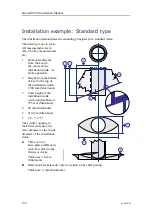
Page 73: ...nical support brackets Due to its height and weight the hull unit gantry must be secured to the bulkhead by means of mechanical support brackets G Transceiver Unit H Heater I Power Supply Unit J Streamlined blister K Three or four knee plates stiffeners must be welded to the frames or decks Stiffen the installation trunk in both the fore and aft and athwartship directions by welding strengthening ...

Page 74: ... Due to its height and weight the hull unit gantry must be secured to the bulkhead by means of mechanical support brackets G Transceiver Unit H Power Supply Unit I Heater J Three or four knee plates stiffeners must be welded to the frames or decks Stiffen the installation trunk in both the fore and aft and athwartship directions by welding strengthening knee plates both to the trunk and to the dou...

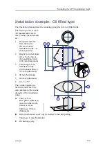
Page 75: ...op of the mounting flange to the bulkhead B Transducer cable C Transducer plug D Transceiver Unit E The location of four knee plates stiffeners on the installation trunk is indicated Stiffen the installation trunk in both the fore and aft and athwartship directions by welding strengthening knee plates both to the trunk and to the doubling plate The shape and locations of the knee plates must be de...

Page 76: ...upport brackets Due to its height and weight the hull unit gantry must be secured to the bulkhead by means of mechanical support brackets G Transceiver Unit H Power Supply Unit I Heater J Streamlined blister K Three or four knee plates stiffeners must be welded to the frames or decks Stiffen the installation trunk in both the fore and aft and athwartship directions by welding strengthening knee pl...

Page 77: ...ort brackets Due to its height and weight the hull unit gantry must be secured to the bulkhead by means of mechanical support brackets G Transceiver Unit H Power Supply Unit I Heater J Three or four knee plates stiffeners must be welded to the frames or decks Stiffen the installation trunk in both the fore and aft and athwartship directions by welding strengthening knee plates both to the trunk an...

Page 78: ... the advanced noise filtering offered by the SC90 we must address the noise challenge This is important during the planning and preparations for the SC90 installation Contributing factors Several factors are contributing to the performance of the hydroacoustic equipment used on board a vessel Factors contributing to the performance of the hydroacoustic equipment used on board a vessel are The qual...

Page 79: ... than noise While SNR is commonly quoted for electrical signals it can be applied to any form of signal http en wikipedia org wiki Signal_to_noise_ratio September 2013 The signal is the echo that we want to know something about while the noise is any unwanted signals or disturbances The echo must be detected in the noise and therefore it is necessary to keep the noise level is as low as possible i...

Page 80: ...or shape The machinery noise can be transmitted to the transducer as Structure borne noise through the ship structure and the transducer mountings Water borne noise through the hull into the water to the transducer Electrical noise Modern vessels are normally equipped with a lot of electric instruments such as hydroacoustic systems radars navigation systems and communication equipment Any electric...

Page 81: ...iscrete frequency while all other flow noise will have a wide frequency spectrum Image from U S Navy in the public domain Flow noise The upper water layers of the sea contain a myriad of small air bubbles created by the breaking waves When the hull moves through water it will cause a disturbance and this will generate friction The friction zone is called the flow boundary layer The flow in this bo...

Page 82: ...f greater or lower amplitude Interference usually refers to the interaction of waves that are correlated or coherent with each other either because they come from the same source or because they have the same or nearly the same frequency Interference effects can be observed with all types of waves for example light radio acoustic surface water waves or matter waves https en wikipedia org wiki Inte...

Page 83: ...s of reverberation Volume reverberation This is caused by minute plankton and air bubbles in the water This reverberation often has daily cycles in intensity Surface and bottom reverberation The surface reverberation is dependent on the weather condition while the bottom reverberation depends on the roughness of the bottom Reverberation is often a limiting factor especially if you are searching fo...

Page 84: ... increases more rapidly and takes over while at higher speed the propeller noise will be the main contributor Note The information here must be considered as general advice Each SC90 installation must be handled separately depending on the hull design and the other electrical and mechanical systems installed on the vessel Reducing flow noise The shape of the transducer or dome around it must be as...

Page 85: ...grounding or by mounting a coal brush from the shaft to vessel ground Reducing rattle noise Ensure that no parts near the transducers can rattle as a result of water flow or vibrations Reducing interference Interference from the transmission pulses from other hydroacoustic instruments on board the vessel is difficult to avoid The problem may be reduced by choosing the working frequencies carefully...

Page 86: ...age 87 Gate valve installation principles page 88 Mechanical support brackets page 89 Installing the mounting flange page 90 Installing the gate valve page 96 Installing the transducer dock page 97 Installing the hydraulic units page 99 Verifying the quality of the gate valve installation page 100 Simrad SC90 Installation Manual ...

Page 87: ...placed on the top of a DN350 Gate Valve using transducer dock 403038 The gate valve is manufactured by LK Valves Gate valve DN350 Manufacturer LK Valves Manufacturer s website http www lkvalves com Technical information about this unit is not included in this SC90 Installation Manual Refer to the relevant end user documentation provided by the manufacturer Both the SC90 and the SC94 Hull Units can...

Page 88: ...ecreased with the height of the mounting flange The SC90 allows you to define a middle position for the transducer When you define the middle position you must take the total height of the gate valve and the mounting flange into consideration Note The installation trunk is not used when a gate valve is mounted The installation trunk is replaced with a transducer dock Drawing file 044140 Mounting f...

Page 89: ...ce prevents the transducer to be lowered while the gate valve is closed It also prevents the gate valve from closing when the transducer is lowered Hydraulic operated gate valve On a hydraulic operated gate valve the control wheel is replaced with a hydraulic motor A Gate valve B Hydraulic Actuator C Hydraulic Power Pack The Hydraulic Power Pack provides the oil pressure for the hydraulic motor on...

Page 90: ...ted to the top of the gate valve Two O rings are used to make the construction water tight The installation shipyard must adapt the mounting flange to fit the shape of the hull or design and manufacture a custom mounting flange Additional knee plates must be added to the final construction Note The installation shipyard must provide all necessary design and installation drawings as well as the rel...

Page 91: ...al size of the complete installation where it is located and the vessel s behaviour in rough sea Note It is very important that the entire installation is sufficiently supported as the forces it is exposed to may affect both the physical installation and the vessel s safety The mechanical support brackets must be designed and manufactured by the installation shipyard to fit the complete installati...

Page 92: ...provided by the installation shipyard to fit the vessel properties The top mating surface of the mounting flange must be protected with a wooden cover at all times until the gate valve is installed It is very important that this surface is clean and undamaged because it must be watertight after the gate valve has been installed Note The quality of the welding is critical to the safety of the vesse...

Page 93: ...it is level undamaged and clean 6 Cover the upper surface of the mounting flange with a wooden plate to protect it 7 Add support frames and stiffeners to secure the construction 8 Depending on the shape of the hull we recommend that you fit a steel blister for protection The blister must be designed by the installation shipyard It must be welded to the shell plating The blister may be an open type...

Page 94: ...ting and all surfaces thoroughly c Make sure that the mating surface is clean and undamaged and well protected until the gate valve is mounted d Check that the offsets are within tolerance Topics Mounting flange and manual gate valve installation page 93 Mounting flange and hydraulic gate valve installation page 94 Installation example page 95 Simrad SC90 Installation Manual ...

Page 95: ...ounting flange and the gate valve are shown The drawings are not to scale A Frames B Knee plates stiffeners C Gate valve A Knee plates stiffeners B Shell plating C As short a possible D O ring E Mounting bolts Nuts Washers F Make sure that the electrical connections to the end switches are easily accessible Installing the optional gate valve DN350 ...

Page 96: ...e valve are shown The drawings are not to scale A Frames B Knee plates stiffeners C Gate valve D Hydraulic Actuator A Knee plates stiffeners B Shell plating C As short a possible D O ring E Mounting bolts Nuts Washers F Make sure that the electrical connections to the end switches and the couplings for the hydraulic hoses are all easily accessible Simrad SC90 Installation Manual ...

Page 97: ...ducer dock F Allow ample space for welding and inspection All measurements are in mm The key measurements are 1 As short a possible 2 As short a possible 3 As short a possible Note The SC90 Hull Unit is designed to lower the transducer 1 0 meter below the ship s hull This depth is decreased with the physical height of the gate valve It is further decreased with the height of the mounting flange Th...

Page 98: ...rtified equipment must be used It is assumed that the mounting flange has been installed correctly Context Only the basic steps of the task are offered Additional procedures with more information and or details must be provided by the installation shipyard to fit the vessel properties The top mating surface of the gate valve must be protected with a wooden cover at all times until the transducer d...

Page 99: ...ghten some of the nuts An alternative is then to use Loctite 270 or similar 6 Lubricate the threads with a high grade commercial anti seize lubricant 7 Lower the valve carefully onto the mounting flange while tightening the nuts 8 Verify that the valve is orientated and aligned correctly 9 Disconnect and remove the tackles from the gate valve 10 Tighten the nuts to torque 472 Nm Installing the tra...

Page 100: ...lled It is very important that this surface is clean and undamaged because it must be watertight after the hull unit has been installed Drawing file 403038 Transducer dock dimensions page 488 430192 Transducer dock dimensions page 491 Procedure 1 Attach the necessary tackles to the transducer dock and make sure that the unit is lifted with the correct side up Verify that the bottom of the transduc...

Page 101: ... additional tools may be required Context On a manually operated gate valve a wheel is used to open and close the valve The wheel is fitted on gate valve which means that you need to go down to the bottom of the vessel to operate it On a hydraulic operated gate valve the control wheel is replaced with a hydraulic motor The hydraulic system comprises the following units Hydraulic Power Pack The Hyd...

Page 102: ...with a wooden cover at all times until the hull unit is installed It is very important that this surface is clean and undamaged because it must be watertight after the hull unit has been installed Objects protruding from the hull will generate turbulence and flow noise This will reduce the SC90 performance Protruding objects may be zinc anodes transducers or even the vessel s keel Holes and pipe o...

Page 103: ...may cause noise 4 Fill in the result tables Result Horizontal distance from the keel to the centre of the installation trunk Height from the bottom of keel to the top of the installation trunk Height of transducer dock Requirements Results All measurements are made and the results are written down The top of the transducer dock is in parallel with the water line The top mating surface on the trans...

Page 104: ...port brackets Date and signature Further requirements If the inspection reveals errors inaccuracies or unfortunate dispositions related to units devices or cables use the Installation remarks form to document these If necessary write a full report and attach high resolution photos Simrad SC90 Installation Manual ...

Page 105: ...5 Gate valve installation principles page 106 Mechanical support brackets page 107 Installing the mounting flange page 108 Installing the gate valve page 113 Installing the transducer dock page 115 Installing the hydraulic units page 99 Verifying the quality of the gate valve installation page 118 Installing the optional gate valve DN500 ...

Page 106: ...al information about this unit is not included in this SC90 Installation Manual Refer to the relevant end user documentation provided by the manufacturer The gate valve is placed at the bottom of the transducer dock It will then increase the total height of the hull unit installation The SC94 Hull Unit is designed to lower the transducer 2 1 meter below the ship s hull This depth is decreased with...

Page 107: ... valve is closed It also prevents the gate valve from closing when the transducer is lowered Hydraulic operated gate valve On a hydraulic operated gate valve the control wheel is replaced with a hydraulic motor A Gate valve B Hydraulic Actuator C Hydraulic Power Pack The Hydraulic Power Pack provides the oil pressure for the hydraulic motor on the gate valve D Gate Valve Control Unit The Gate Valv...

Page 108: ...e shape of the hull or design and manufacture a custom mounting flange Additional knee plates must be added to the final construction Note The installation shipyard must provide all necessary design and installation drawings as well as the relevant work standards and mounting procedures If required all drawings and documents must be approved by the vessel s national registry and corresponding mari...

Page 109: ...It is very important that the entire installation is sufficiently supported as the forces it is exposed to may affect both the physical installation and the vessel s safety The mechanical support brackets must be designed and manufactured by the installation shipyard to fit the complete installation in the sonar room We recommend that support brackets are placed pointing at minimum three direction...

Page 110: ... provided by the installation shipyard to fit the vessel properties The top mating surface of the mounting flange must be protected with a wooden cover at all times until the gate valve is installed It is very important that this surface is clean and undamaged because it must be watertight after the gate valve has been installed Note The quality of the welding is critical to the safety of the vess...

Page 111: ...it is level undamaged and clean 6 Cover the upper surface of the mounting flange with a wooden plate to protect it 7 Add support frames and stiffeners to secure the construction 8 Depending on the shape of the hull we recommend that you fit a steel blister for protection The blister must be designed by the installation shipyard It must be welded to the shell plating The blister may be an open type...

Page 112: ...ing and all surfaces thoroughly c Make sure that the mating surface is clean and undamaged and well protected until the gate valve is mounted d Check that the offsets are within tolerance Topics Mounting flange and manual gate valve installation page 111 Mounting flange and hydraulic gate valve installation page 112 Installation example page 113 Simrad SC90 Installation Manual ...

Page 113: ...ounting flange and the gate valve are shown The drawings are not to scale A Frames B Knee plates stiffeners C Gate valve A Knee plates stiffeners B Shell plating C As short a possible D O ring E Mounting bolts Nuts Washers F Make sure that the electrical connections to the end switches are easily accessible Installing the optional gate valve DN500 ...

Page 114: ...e valve are shown The drawings are not to scale A Frames B Knee plates stiffeners C Gate valve D Hydraulic Actuator A Knee plates stiffeners B Shell plating C As short a possible D O ring E Mounting bolts Nuts Washers F Make sure that the electrical connections to the end switches and the couplings for the hydraulic hoses are all easily accessible Simrad SC90 Installation Manual ...

Page 115: ...le Note The SC94 Hull Unit is designed to lower the transducer 2 1 meter below the ship s hull This depth is decreased with the physical height of the gate valve It is further decreased with the height of the mounting flange Installing the gate valve The gate valve must be mounted so that its top mating surface is in parallel with the sea surface during normal operating conditions The transducer d...

Page 116: ... the transducer dock has been installed Procedure 1 Attach the necessary tackles to the gate valve and make sure that the unit is lifted with the correct side up The gate valve will work in any position but we recommend that it is mounted with its identification tags and classification markings facing up You must also consider the access to the end switches and if relevant the hydraulic hose conne...

Page 117: ...This task must take place in dry dock The shipyard must provide all necessary tools and manpower The following specific items are required for this task Silicone grease Anti seize lubricant Torque wrench Lifting arrangement O ring Mounting hardware It is assumed that the gate valve has been installed Note The transducer dock is heavy Always use appropriate lifting equipment to minimize risk of per...

Page 118: ...faces 3 Prepare the gate valve a Remove the protective cover from the mating surface on the gate valve b Verify that the mating surface on the gate valve is clean and undamaged c Wipe a thin film of silicone grease on the O ring and place it in the groove on the gate valve 4 Attach the nuts and washers while the transducer dock is still suspended 5 Lubricate the threads with a high grade commercia...

Page 119: ... comprises the following units Hydraulic Power Pack The Hydraulic Power Pack provides the oil pressure for the hydraulic motor on the gate valve Gate Valve Control Unit The Gate Valve Control Unit provides local control of the Hydraulic Power Pack It contains controllers to operate the entire gate valve system Remote Control Unit Optional The Remote Control Unit allows you to operate the gate valv...

Page 120: ...reduce the SC90 performance Protruding objects may be zinc anodes transducers or even the vessel s keel Holes and pipe outlets are also important noise sources as well as rough surfaces caused by bad welding Even traces of sealing compound sharp edges bolts or empty bolt holes will create noise The following requirements must be met All measurements are made and the results are written down The to...

Page 121: ... in parallel with the water line The top mating surface on the transducer dock is clean without sand dust or any other destructive particles Is is even and smooth without scratches dents or other physical damage The gasket or O ring on the top of the transducer dock is not damaged The installation of the gate valve has left enough space to access end switches and if relevant hydraulic connections ...

Page 122: ...ics About the installation trunk page 121 Mounting the installation trunk page 123 Verifying the quality of the installation page 126 Installation example Standard type page 128 Installation example Oil filled type page 129 Simrad SC90 Installation Manual ...

Page 123: ...ation trunks are used Installation trunk Upper diame ter Bottom diam eter Part number Drawing Blind panel SC90 370 mm 273 mm 408615 402509 051344 SC94 760 mm 610 mm 427423 427176 207485 SC94 760 mm 356 mm 434529 434524 207485 The installation trunk with a blind cover can be ordered from Kongsberg Maritime as an optional delivery As an alternative the installation trunk can be manufactured by the s...

Page 124: ...support brackets The dimensions and strength of the support brackets must be adequate to prevent vortex induced vibration This a requirement to ensure the safety of the SC90 and the vessel The forces to which the hull unit is exposed depends on the physical size of the installation where it is located and the vessel s behaviour in rough sea It is very important that the hull unit is sufficiently s...

Page 125: ...tallation trunk must be mounted so that it remains vertical during normal operating conditions Prerequisites This task must take place in dry dock The shipyard must provide all necessary tools and manpower Illustration The centre line of the trunk must be parallel with the vessel s centre line The installation trunk is heavy Always use appropriate lifting equipment to minimize risk of personnel in...

Page 126: ...llation trunk with regards to the mounting bolts 3 Remove the rubber gasket from the top of the installation trunk to protect it from the heat 4 Cut out a hole in the vessel s hull with a diameter large enough to accommodate the installation trunk The exact size of the hole must be determined by the installation shipyard 5 Orientate the installation trunk correctly and then weld it into position O...

Page 127: ...d by the installation shipyard It must be welded to the shell plating The blister may be an open type or it can be filled with oil to prevent corrosion This last method provides excellent protection and simplifies maintenance Note Make sure that the hull plating surrounding the trunk is even and smooth without protruding objects that can cause noise Objects protruding from the hull will generate t...

Page 128: ... and pipe outlets are also important noise sources as well as rough surfaces caused by bad welding Even traces of sealing compound sharp edges bolts or empty bolt holes will create noise Procedure 1 Write down the key measurements This is for future reference Horizontal distance from the keel to the centre of the installation trunk Height from the bottom of keel to the top of the installation trun...

Page 129: ...es dents or other physical damage The installation trunk has been properly stiffened in both the fore and aft and athwartship directions by means of strengthening knee plates The installation trunk has been properly braced to the hull plating and the surrounding hull frames The hull plating surrounding the installation trunk is even and smooth without protruding objects that can cause noise The ga...

Page 130: ...le 2 Height from the bottom of keel to the top of the installation trunk 1440 mm Maximum 3 Total height of the installation trunk with optional blister 970 mm Minimum The circular opening in the blister must have the same diameter as the inside diameter of the installation trunk A Three or four knee plates stiffeners must be welded to the frames or decks Thickness 10 mm Minimum B Deflection bracke...

Page 131: ...t from the bottom of keel to the top of the installation trunk 1440 mm Maximum 3 Total height of the installation trunk with optional blister 970 mm Minimum The circular opening in the blister must have the same diameter as the inside diameter of the installation trunk A Three or four knee plates stiffeners must be welded to the frames or decks Thickness 10 mm Minimum B Deflection brackets must on...

Page 132: ...ics About the installation trunk page 131 Mounting the installation trunk page 133 Verifying the quality of the installation page 126 Installation example Standard type page 138 Installation example Oil filled type page 139 Simrad SC90 Installation Manual ...

Page 133: ...Due to the different flange diameters different installation trunks are used Installation trunk Upper diame ter Bottom diam eter Part number Drawing Blind panel SC90 370 mm 273 mm 408615 402509 051344 SC94 760 mm 610 mm 427423 427176 207485 SC94 760 mm 356 mm 434529 434524 207485 The installation trunk with a blind cover can be ordered from Kongsberg Maritime as an optional delivery As an alternat...

Page 134: ...the installation trunk penetrates the vessel hull it is very important that the hull unit is installed and secured properly Important The hull unit gantry must be secured to the bulkhead by means of mechanical support brackets The dimensions and strength of the support brackets must be adequate to prevent vortex induced vibration This a requirement to ensure the safety of the SC90 and the vessel T...

Page 135: ...n begin The shipowner and shipyard doing the installation are responsible for obtaining and paying for such approval Mounting the installation trunk The installation trunk must be mounted so that it remains vertical during normal operating conditions Prerequisites This task must take place in dry dock The shipyard must provide all necessary tools and manpower Illustration The centre line of the tr...

Page 136: ...llation trunk with regards to the mounting bolts 3 Remove the rubber gasket from the top of the installation trunk to protect it from the heat 4 Cut out a hole in the vessel s hull with a diameter large enough to accommodate the installation trunk The exact size of the hole must be determined by the installation shipyard 5 Orientate the installation trunk correctly and then weld it into position O...

Page 137: ...d by the installation shipyard It must be welded to the shell plating The blister may be an open type or it can be filled with oil to prevent corrosion This last method provides excellent protection and simplifies maintenance Note Make sure that the hull plating surrounding the trunk is even and smooth without protruding objects that can cause noise Objects protruding from the hull will generate t...

Page 138: ... and pipe outlets are also important noise sources as well as rough surfaces caused by bad welding Even traces of sealing compound sharp edges bolts or empty bolt holes will create noise Procedure 1 Write down the key measurements This is for future reference Horizontal distance from the keel to the centre of the installation trunk Height from the bottom of keel to the top of the installation trun...

Page 139: ...es dents or other physical damage The installation trunk has been properly stiffened in both the fore and aft and athwartship directions by means of strengthening knee plates The installation trunk has been properly braced to the hull plating and the surrounding hull frames The hull plating surrounding the installation trunk is even and smooth without protruding objects that can cause noise The ga...

Page 140: ...ttom of keel to the top of the installation trunk 1200 mm Maximum 3 Total height of the installation trunk with optional blister 795 mm Minimum 4 40 mm Minimum 5 610 mm Minimum 6 2 5 3 x 5 The circular opening in the blister must have the same diameter as the inside diameter of the installation trunk A Three or four knee plates stiffeners must be welded to the frames or decks Thickness 10 mm Minim...

Page 141: ...el to the top of the installation trunk 1200 mm Maximum 3 Total height of the installation trunk with optional blister 795 mm Minimum 4 40 mm Minimum 5 610 mm Minimum 6 2 5 3 x 5 The circular opening in the blister must have the same diameter as the inside diameter of the installation trunk A Three or four knee plates stiffeners must be welded to the frames or decks Thickness 10 mm Minimum B Defle...

Page 142: ...it from its transport box page 148 Mounting the hull unit on top of the installation trunk page 150 Designing and mounting mechanical support brackets to secure the hull unit page 152 Hull unit and transducer alignment page 154 Inspecting the transducer page 154 Verifying the quality of the hull unit installation page 155 Simrad SC90 Installation Manual ...

Page 143: ...ant that the hull unit is installed and secured properly The hull unit shall be mounted on top of the installation trunk at the bottom of the hull The installation trunk penetrates the ship s hull and allows the transducer to be lowered into the sea The hull unit is normally located in the forward part of the vessel The installation trunk is not used when a gate valve is mounted The installation t...

Page 144: ...hanical support brackets must be designed and manufactured by the installation shipyard to fit the complete installation in the sonar room All calculations made to support the design must meet the applicable safety requirements and apply to the physical properties of the hull and the installation Note The final design and the installation must be approved by the classification society Without a pr...

Page 145: ...ed all documents provided by the shipyard for the physical installation of the SC90 must be approved by the vessel s national registry and corresponding maritime authority and or classification society Such approval must be obtained before the installation can begin The shipowner and shipyard doing the installation are responsible for obtaining and paying for such approval Installing the SC90 Hull...

Page 146: ... transducer dock and a gate valve additional support brackets must be installed from the top of the mounting flange to the bulkhead B Transducer cable C Transducer plug D Transceiver Unit E The location of four knee plates stiffeners on the installation trunk is indicated Stiffen the installation trunk in both the fore and aft and athwartship directions by welding strengthening knee plates both to...

Page 147: ...er is 25 mm C Air vent pipe minimum diameter is 25 mm D Access hatch E Lamp F Mechanical support brackets Due to its height and weight the hull unit gantry must be secured to the bulkhead by means of mechanical support brackets G Transceiver Unit H Power Supply Unit I Heater J Three or four knee plates stiffeners must be welded to the frames or decks Stiffen the installation trunk in both the fore...

Page 148: ...r is 25 mm C Air vent pipe minimum diameter is 25 mm D Access hatch E Lamp F Mechanical support brackets Due to its height and weight the hull unit gantry must be secured to the bulkhead by means of mechanical support brackets G Transceiver Unit H Heater I Power Supply Unit J Streamlined blister K Three or four knee plates stiffeners must be welded to the frames or decks Stiffen the installation t...

Page 149: ...p of the installation trunk The SC90 transducer is bolted to the bottom of the transducer shaft The transducer cables are placed inside the shaft A Location of the Upper Limit Switch B Location of the Lower Limit Switch C Transducer cable with plug D Transducer shaft E Grease nipple with pressure release plug on the rear side F Air bleeding cock G Hoisting motor H Motor Control Unit I Gantry J Mou...

Page 150: ...le crane or ship s crane is required Always use appropriate lifting equipment to minimize risk of personnel injury or equipment damages Only certified equipment must be used Context The hull unit transducer and transducer cable must be handled with care Note The transducer is protected with a thick layer of foam to prevent damage during transport and hull unit installation This protection must rem...

Page 151: ...ng eye There are two lifting eyes on each side of the hull unit One is located on the top of the gantry and one on the top of the transducer shaft Make sure that you use the lifting eye on the gantry when you lift the hull unit out of the transport box 6 While lifting make sure that you do not damage the delicate parts of the hull unit Note Make sure that you keep the transducer safe and the trans...

Page 152: ...njury or equipment damages Only certified equipment must be used Context As a general recommendation the hull unit shall be oriented with the hoist lower motor pointing aft If this orientation makes it difficult to access the Motor Control Unit the hull unit may be rotated to the most suitable direction The hull unit transducer and transducer cable must be handled with care Note The transducer is ...

Page 153: ...e transducer protection still in place and place it vertically over the installation trunk 2 While lifting make sure that you do not damage the delicate parts of the hull unit Note Make sure that you keep the transducer safe and the transducer cable and connector dry Watch these carefully to prevent these delicate parts from being damaged stuck or hooked on to protruding objects while manoeuvring ...

Page 154: ... prevent vortex induced vibration This a requirement to ensure the safety of the SC90 and the vessel Prerequisites The shipyard must provide all necessary tools and manpower Context A Removable support brackets B Bulkhead C Hull Unit The forces to which the hull unit is exposed depends on the physical size of the installation where it is located and the vessel s behaviour in rough sea It is very i...

Page 155: ... bolts b Verify that it is possible to remove the support brackets if maintenance is required c Verify that the transducer cable is not obstructed by the support brackets 4 If applicable a Do a close visual inspection of the physical properties of the installation trunk and the way it has been installed b Make sure that the installation trunk has been properly braced to the hull plating and the su...

Page 156: ...ontext A Lower part of transducer shaft B Transducer with its red protective coating The transducer is covered with a thick red protective coating made of a special plastic type The red protective coating is an vital part of the transducer It is very important that neither this coating nor the internal parts of the transducer are damaged during the handling installation or cleaning Any holes and o...

Page 157: ...rom the stub shaft and mount it in its storage position in the Motor Control Unit Result Requirements Results The transducer is new clean and free from scratches dents or other physical damage Date and signature Verifying the quality of the hull unit installation A quality inspection must take place after the hull unit has been installed and while the vessel is still in dry dock The inspection sha...

Page 158: ...flat and shake proof washers have been used f Make sure that all nuts have been tightened properly g Make sure that all welds and brackets have been painted with the correct preservation medium to prevent corrosion 4 Make sure that cable installation has been completed a Make sure that all cables leading to and from the unit have been properly mounted and secured b Make sure that the unit is secur...

Page 159: ... mechanical brackets that support the gantry are strong enough to hold the hull unit securely in place under all operating conditions If a gate valve is used the welds and mechanical brackets that support the mounting flange are strong enough to hold the hull unit securely in place under all operating conditions The welds and brackets have been painted with the correct preservation medium to preve...

Page 160: ...65 Mounting the hull unit on top of the installation trunk page 167 Connecting a ventilation pipe to the air bleeding cock page 169 Designing and mounting mechanical support brackets to secure the hull unit page 170 Hull unit and transducer alignment page 171 Inspecting the transducer page 172 Verifying the quality of the hull unit installation page 173 Simrad SC90 Installation Manual ...

Page 161: ...ll and allows the transducer to be lowered into the sea The hull unit is normally located in the forward part of the vessel The installation trunk is not used when a gate valve is mounted The installation trunk is replaced with a transducer dock Relevant cranes and lifting equipment must be available Free access through the hull or the decks onto the top of the installation trunk must be provided ...

Page 162: ...allation trunk and the bottom of the transducer shaft sleeve During the installation process make sure that this gasket is kept safe from damage and that the top of the installation trunk is kept clean smooth and without physical damage such as scratches or dents Proper O ring lubrication must be applied before the hull unit is mounted on top of the installation trunk and gasket Design and install...

Page 163: ...a transducer dock and a gate valve additional support brackets must be installed from the top of the mounting flange to the bulkhead B Transducer cable C Transducer plug D Transceiver Unit E The location of four knee plates stiffeners on the installation trunk is indicated Stiffen the installation trunk in both the fore and aft and athwartship directions by welding strengthening knee plates both t...

Page 164: ...nical support brackets Due to its height and weight the hull unit gantry must be secured to the bulkhead by means of mechanical support brackets G Transceiver Unit H Power Supply Unit I Heater J Three or four knee plates stiffeners must be welded to the frames or decks Stiffen the installation trunk in both the fore and aft and athwartship directions by welding strengthening knee plates both to th...

Page 165: ...hanical support brackets Due to its height and weight the hull unit gantry must be secured to the bulkhead by means of mechanical support brackets G Transceiver Unit H Power Supply Unit I Heater J Streamlined blister K Three or four knee plates stiffeners must be welded to the frames or decks Stiffen the installation trunk in both the fore and aft and athwartship directions by welding strengthenin...

Page 166: ...is mounted on top of the installation trunk The SC90 transducer is bolted to the bottom of the transducer shaft The transducer cables are placed inside the shaft A Location of the Upper Limit Switch B Location of the Lower Limit Switch C Transducer cable with plug D Transducer shaft E Transducer shaft sleeve F Air bleeding cock G Hoisting motor H Motor Control Unit I Gantry J Mounting flange K Ins...

Page 167: ...ble crane or ship s crane is required Always use appropriate lifting equipment to minimize risk of personnel injury or equipment damages Only certified equipment must be used Context The hull unit transducer and transducer cable must be handled with care Note The transducer is protected with a thick layer of foam to prevent damage during transport and hull unit installation This protection must re...

Page 168: ...g eye There are two lifting eyes on each side of the hull unit One is located on the top of the gantry and one on the top of the transducer shaft Make sure that you use the lifting eye on the gantry when you lift the hull unit out of the transport box 6 While lifting make sure that you do not damage the delicate parts of the hull unit Note Make sure that you keep the transducer safe and the transd...

Page 169: ...injury or equipment damages Only certified equipment must be used Context As a general recommendation the hull unit shall be oriented with the hoist lower motor pointing aft If this orientation makes it difficult to access the Motor Control Unit the hull unit may be rotated to the most suitable direction The hull unit transducer and transducer cable must be handled with care Note The transducer is...

Page 170: ... transducer protection still in place and place it vertically over the installation trunk 2 While lifting make sure that you do not damage the delicate parts of the hull unit Note Make sure that you keep the transducer safe and the transducer cable and connector dry Watch these carefully to prevent these delicate parts from being damaged stuck or hooked on to protruding objects while manoeuvring t...

Page 171: ... may damage the transducer The hull unit mounting flange is provided with an dedicated cock to release any trapped air from inside the trunk Prerequisites The shipyard must provide all necessary tools and manpower The following specific item is required for this task Ventilation pipe Inner diameter 10 mm Minimum The following special tools are required for this task Plumbing tools A Ventilation pi...

Page 172: ...fficiently supported as the forces it is exposed to may affect both the physical installation and the vessel s safety The mechanical support brackets must be designed and manufactured by the installation shipyard to fit the complete installation in the sonar room All calculations made to support the design must meet the applicable safety requirements and apply to the physical properties of the hul...

Page 173: ...g hull frames c Make sure that the installation trunk has been properly stiffened in both the fore and aft and athwartship directions by means of strengthening knee plates 5 If applicable a Do a close visual inspection of the mounting flange gate valve and transducer dock and inspect the way they have been installed b Make sure that the transducer dock has been properly braced to the hull plating ...

Page 174: ... Lower the transducer using the hand crank a Locate the hand crank inside the Motor Control Unit b Remove the hand crank from its storage position c Remove the plastic plug on the top cover of the hull unit d Mount the hand crank onto the stub shaft through the hole in the top cover e Use the hand crank to lower the transducer 2 Do a thorough visual inspection of the transducer Check for dents scr...

Page 175: ...ed in the correct location and that it is suitably oriented for easy maintenance and replacement of parts 2 Make sure that the unit is not physically damaged and that the paint work is clean without dents or scratches The physical handling of the unit during the installation may have caused some minor scratches to the paint work This can be accepted However if rough handling has caused serious dam...

Page 176: ...nstallation trunk support brackets or other parts of the installation 6 Fill in the result table Result Requirements Results The compartment in which the hull unit is installed sonar room is clean and dry The sonar room meets all requirements related to the vessel s watertight integrity The sonar room meets all size and access requirements The access hatches are suitably constructed and located Th...

Page 177: ...lds and brackets have been painted with the correct preservation medium to prevent corrosion There are no corrosive attacks Date and signature Further requirements If the inspection reveals errors inaccuracies or unfortunate dispositions related to units devices or cables use the Installation remarks form to document these If necessary write a full report and attach high resolution photos Installi...

Page 178: ...e display page 177 Installing the Enix Processor Unit page 178 Installing the Operating Panel page 180 Installing the Operating Panel Power Supply page 182 Installing the Power Supply Unit page 183 Installing the Transceiver Unit page 184 Simrad SC90 Installation Manual ...

Page 179: ...sary tools 2 Observe the installation requirements a Position the display so that it is best protected from glare which reduces readability b Mount the display as recommended by the manufacturer recessed in a panel on the desktop or bulkhead or overhead c Observe the compass safe distance d Make sure that enough space is made available for maintenance purposes e Make sure that adequate ventilation...

Page 180: ...your equipment A suitable location for the Processor Unit must be defined prior to installation Observe the compass safe distance A The bottom plate is mounted with six bolts through the computer chassis B Each rail provides two holes for mounting to a flat surface C Remove this bolt to release the rail from the bottom plate Context If you intend to mount the Enix Processor Unit in a 19 rack you c...

Page 181: ...placement If relevant make sure that the space allows you to open the computer for unobstructed access to its internal parts Note Make sure that you can access both the rear and front side of the computer after it has been installed 5 Install the computer a Turn the Processor Unit cabinet upside down and remove the bottom plate A with the shock absorbers b Observe the four holes in the shock absor...

Page 182: ...echanical tasks This includes different screwdriver types pliers spanners a cable stripper a soldering iron etc Each tool must be provided in various sizes We recommend that all tools are demagnetized to protect your equipment Depending on the chosen installation method additional tools may be required Context A suitable location for the Operating Panel must be chosen before the installation start...

Page 183: ...wn in the illustration b Use a 3 mm Allen key to fasten the four special bolts c Mount the bolt covers in the four corners of the Operating Panel 4 Connect the cables Note When you connect the cables make sure that they are all properly secured and able to withstand the vibration and movements of the vessel Topics Operating Panel cut out drawing page 181 Operating Panel cut out drawing All measure...

Page 184: ...chosen installation method additional tools may be required Context A suitable location for the Operating Panel Power Supply must be defined before the installation can start Any location can be used provided that the cables are long enough and that the ventilation is adequate The power supply connects to the rear side of the Processor Unit Procedure 1 Prepare the location and the necessary tools ...

Page 185: ... chosen installation method additional tools may be required Context A suitable location for the unit must be defined before the installation can start Free bulkhead space is required Any location can be used provided that the cables are long enough and that the ventilation is adequate The chosen location must allow ample space for installation and maintenance tasks Make sure that the cabinet door...

Page 186: ...page 447 Installing the Transceiver Unit The SC90 Transceiver Unit is normally positioned close to the hull unit It can also be installed in a dedicated compartment The physical length of the transducer cable limits the distance between the hull unit and the Transceiver Unit Prerequisites You must be equipped with a standard set of tools This tool set must comprise the normal tools for electronic ...

Page 187: ...may need to move the power outlet or replace the power cable with a longer type Note The Transceiver Unit is heavy Make sure that the necessary manpower and lifting equipment are available before you start the installation work The Transceiver Unit must be mounted as a complete unit The cabinet door must not be opened until the unit is securely fastened to the bulkhead Procedure 1 Prepare the loca...

Page 188: ...lastic bag fastened to the upper shock absorber 5 Weld the mounting brackets securely to the bulkhead as shown in the illustrations 6 Use a chain fall or similar device to lift the Transceiver Unit into position 7 Bolt the cabinet to the mounting brackets Eight bolts are provided for this purpose 8 Connect the grounding cable from the Transceiver Unit to the mounting bracket 9 Do not connect any o...

Page 189: ...50 B 187 Location of the mounting brackets A Deckhead B Bulkhead C Deck D Angle bars with threaded holes for shock absorbers These bars are supplied by Kongsberg Maritime Installing the SC90 hardware units ...

Page 190: ...419050 B Installation of the mounting brackets A Deckhead B Bulkhead C Deck D Angle bars with threaded holes for shock absorbers These bars are supplied by Kongsberg Maritime Simrad SC90 Installation Manual ...

Page 191: ...19050 B 189 Connecting the Transceiver Unit to vessel ground A Upper shock absorber B Transceiver Unit cabinet C Cabinet door D Grounding cable E Grounding cable detail Installing the SC90 hardware units ...

Page 192: ... List of SC90 cables page 195 Installing the SC90 cables page 198 Processor Unit graphic adapter page 208 Processor Unit serial adapter page 210 Serial line splitters page 213 Setting up the SC90 in a synchronized system page 222 Cable drawings and specifications page 228 Basic cable requirements page 257 Simrad SC90 Installation Manual ...

Page 193: ...lectronic installations and corresponding wiring must be in accordance with the vessel s national registry and corresponding maritime authority and or classification society If no such guidelines exist we recommend that Det Norske Veritas DNV GL Report No 80 P008 Guidelines for Installation and Proposal for Test of Equipment is used as a guide Note It is very important that all cables are properly...

Page 194: ...rocessor Unit to the Transceiver Unit is 100 meters It is very important that a high quality Ethernet cable is used You must use CAT 5E STP Shielded Twisted Pair quality or better Using a cable with lower bandwidth capacity will reduce the SC90 performance Do not connect the Processor Unit to the Transceiver Unit using an existing local area network LAN Tip Even though only one Ethernet cable is u...

Page 195: ...l Unit E Transducer cable One high capacity Ethernet cable connects the Processor Unit to the Transceiver Unit Cables identified with an asterisk are system cables These cables are supplied with the SC90 delivery The maximum length of the Ethernet cable from the Processor Unit to the Transceiver Unit is 100 meters It is very important that a high quality Ethernet cable is used You must use CAT 5E ...

Page 196: ...194 419050 B Related topics Topside cable plan page 192 Sonar room cable plan page 193 List of SC90 cables page 195 Simrad SC90 Installation Manual ...

Page 197: ...nel to vessel ground 1 x 6 mm Ethernet cable From Processor Unit to Transceiver Unit CAT5 E STP Shielded Twisted Pair C8 The maximum length of the Ethernet cable from the Processor Unit to the Transceiver Unit is 100 meters It is very important that a high quality Ethernet cable is used You must use CAT 5E STP Shielded Twisted Pair quality or better Using a cable with lower bandwidth capacity will...

Page 198: ...2 metres Control cable From Motor Control Unit to gate valve and Gate Valve Control Unit C21 This connection is only required if the optional hydraulic gate valve is installed This interface prevents the transducer to be lowered while the gate valve is closed It also prevents the gate valve from closing when the transducer is lowered C22 AC power cable From Transceiver Unit to uninterruptible powe...

Page 199: ...cable for the Transceiver Unit is not listed The grounding cable is a special braided wire that is physically connected to the cabinet It is connected to vessel ground by means of the cabinet s shock absorbers More than one serial line cable may be required to connect the Processor Unit to external devices To identify these cables use postfix letters C13A C13B C13C The SC90 is often a part of a pr...

Page 200: ... various sizes We recommend that all tools are demagnetized to protect your equipment Depending on the tasks at hand additional tools may be required Refer to the cable plans and the list of cables Detailed information about cable specifications termination and connectors are provided in the relevant cable drawings Unless otherwise specified all cables are provided with the SC90 delivery In order ...

Page 201: ... Connect the power cable from the Processor Unit to the Operating Panel Power Supply C4 e Connect the power cable from the Operating Panel Power Supply to the power outlet on the uninterruptible power supply UPS C5 Standard commercial AC mains cables are used Each cable is supplied with the relevant unit The typical cable length is between 1 5 and 2 meters If this is too short you must use an exte...

Page 202: ...t the various video standards explore these Wikipedia pages DVI HDMI DisplayPort 4 Connect the control cables from the Processor Unit to the Operating Panel C10 C11 C12 The control cables between the Operating Panel and the Processor Unit are provided with the SC90 delivery For more information see the cable details Communication and power cable for the Operating Panel page 245 5 Connect the Ether...

Page 203: ...K Sync interface to generic RS 232 synchronization input page 241 Simrad TU40 interface to generic RS 232 synchronization input page 243 8 If applicable make the relevant connections to enable the Emergency hoist functionality Emergency hoist functionality is provided by the Hull Unit Control circuit board in the Motor Control Unit We does not offer any optional products or kits to put this functi...

Page 204: ...ur own power cable with sufficient length For more information see the cable details AC power cable using IEC C13 inline socket page 229 2 Connect the ground cable from the Power Supply Unit to vessel ground C30 This cable must be provided by the installation shipyard For more information see the cable details Ground cable page 231 3 Connect the ground cable from the Transceiver Unit to vessel gro...

Page 205: ...sducer to be lowered while the gate valve is closed It also prevents the gate valve from closing when the transducer is lowered For more information see the cable details Connection between the gate valve and the Motor Control Unit page 252 10 Prepare the installation of the transducer cable The transducer cables are connected to the Transceiver Unit using a large transceiver plug The transceiver ...

Page 206: ...the display and terminated in the computer end with a male connector If the cable is not attached it is normally provided with the display If you need to use a DVI to SVGA adapter to connect your display you must use the left DVI I output This is the only output that supports the SVGA signals C Video cable D Serial cables From Processor Unit to external device s C13 E Not used F Ethernet cable Fro...

Page 207: ...or in the Processor Unit end A plug I Ethernet cable From Processor Unit to local area network LAN C14 If you wish to connect the Processor Unit to the ship s local area network use the left Ethernet socket on the connection panel Do not use the adapter in Slot F J Ground cable From Processor Unit to vessel ground C6 K AC power cable From Processor Unit to uninterruptible power supply UPS C3 L Aud...

Page 208: ...ransceiver Unit to Power Supply Unit C29 C Ethernet cable From Transceiver Unit to Processor Unit C8 D DC power cable From Transceiver Unit to Power Supply Unit C26 E AC power cable From Transceiver Unit to uninterruptible power supply UPS C22 Note DO NOT connect the transceiver plug to the socket on the Transceiver Unit This connection is made as a part of the Setting to work procedures Related t...

Page 209: ...Unit to Transceiver Unit C29 B DC power cable From Power Supply Unit to Transceiver Unit C26 C AC power cable From Power Supply Unit to uninterruptible power supply UPS C24 D Ground cable From Power Supply Unit to vessel ground C30 Related topics Installing the SC90 sonar room cables page 202 Installing the SC90 cables page 198 Cable layout and interconnections ...

Page 210: ...ine Apart from the variety of output ports the two sets of Mini DP and DVI outputs allow old systems to be upgraded directly to multi display solutions The ER93F Graphic Card uses the embedded E6760 graphics chip from AMD and incorporates 128 bit 1GB GDDR5 memory in MCM BGA packaging Industrial grade passive electronic components are used throughout the entire card and it has been tested between 2...

Page 211: ...ish to connect a standard VGA display using a DVI to VGA adapter you must use the left output D Graphic output resolutions The following output resolutions are provided Display Port Maximum resolution 2560 x 1600 px HDMI Maximum resolution 1920 x 1200 px DVI I D Maximum resolution 2560 x 1600 px VGA using adapter Maximum resolution 2048 x 1536 px Tip To learn more about the various video standards...

Page 212: ...232 RS 422 and RS 485 both 2 and 4 wire The connections to the board are made using a converter cable with four 9 pin male D connectors The converter cable is supplied with the Processor Unit Manufacturer Moxa Manufacturer s website http www moxa com Serial line support The Moxa CP114EL I serial adapter supports the following interface formats Port 1 RS 232 RS 422 RS 485 Port 2 RS 232 RS 422 RS 48...

Page 213: ...pin D connectors To make the individual connections easier four 9 pin D sub connectors with screw terminals and a number of adapter nuts for connection to the adapter cable are also included in the delivery Pin assignments Moxa CP114EL I 9 pin D connector converter Pin RS 232 RS 422 RS485 4 wire RS485 2 wire 1 DCD TXD A TXD A 2 RxD TXD B TXD B 3 TxD RXD B RXD B Data B 4 DTR RXD A RXD A Data A 5 GN...

Page 214: ...scribed Procedure 1 Click Start Settings Control Panel 2 In the Control Panel dialog box click System 3 In the System Properties dialog box click the Hardware tab then click Device Manager 4 In the Device Manager dialog box expand the Multi port serial adapters option and double click Moxa CP114EL Series PCI Express Bus to open the configuration utility 5 Observe that the dedicated properties dial...

Page 215: ...nections page 220 Øverland UPC 5000P Dimensions page 221 About serial line splitters On large installations with many hydrographic systems these systems often require the same navigational information from a single sensor As an example information such as the current depth or speed is provided as datagrams on a serial line format One or more serial line splitters are then used to distribute the in...

Page 216: ...isolated from the outputs All outputs are Short Circuit Protected Information from the manufacturer s website copied January 2017 The serial line splitter is fitted with a DIN rail for easy mounting and replacement Note The serial line splitter requires a dedicated power supply providing 15 to 30 VDC For more information about this serial line splitter consult the manufacturer s website Manufactur...

Page 217: ...outputs from the serial line splitter are short circuit protected Installation The serial line splitter is fitted with a DIN rail for easy mounting and replacement Outline dimensions Length 130 mm Width 80 mm Height 50 mm Note This information was copied from the manufacturer s documentation The technical specifications may be changed without prior notice To ensure that your information is correct...

Page 218: ...cated power supply providing 15 to 30 VDC A Power requirements 15 30 VDC B Input C Outputs 3 x RS 232 D Outputs 5 x RS 422 Note This information was copied from the manufacturer s documentation The technical specifications may be changed without prior notice To ensure that your information is correct always consult the manufacturer s own documents Simrad SC90 Installation Manual ...

Page 219: ...419050 B 217 Øverland UPC 3005 Dimensions Cable layout and interconnections ...

Page 220: ...is idle The power supply and both signal inputs are galvanic isolated from the outputs All outputs are short circuit protected Information from the manufacturer s data sheet copied May 2014 The serial line splitter is fitted with a DIN rail for easy mounting and replacement Note The serial line splitter requires a dedicated power supply providing 15 to 30 VDC For more information about this serial...

Page 221: ...x RS 422 Maximum 50 mA 5 x RS 232 All outputs from the serial line splitter are short circuit protected For Current Loop input 100 Ω Parallel Installation The serial line splitter is fitted with a DIN rail for easy mounting and replacement Outline dimensions Length 128 mm Width 128 mm Height 50 mm Note This information was copied from the manufacturer s documentation The technical specifications m...

Page 222: ...r supply providing 15 to 30 VDC A Outputs 5 x RS 232 B Relay NO NC by internal strap C Input D Power requirements 15 30 VDC E Outputs 10 x RS 422 Note This information was copied from the manufacturer s documentation The technical specifications may be changed without prior notice To ensure that your information is correct always consult the manufacturer s own documents Simrad SC90 Installation Ma...

Page 223: ...419050 B 221 Øverland UPC 5000P Dimensions Cable layout and interconnections ...

Page 224: ...controls all the transmissions In physics interference is the phenomenon in which two waves superpose each other to form a resultant wave of greater or lower amplitude Interference usually refers to the interaction of waves that are correlated or coherent with each other either because they come from the same source or because they have the same or nearly the same frequency Interference effects ca...

Page 225: ...ronization port The Delay setting is not applicable when synchronization is switched off Master The Master mode is used if the SC90 shall act as the controlling unit in a synchronized system The peripheral hydroacoustic system s are only permitted to transmit when enabled by the SC90 When the Master mode is chosen the SC90 will run using its internal ping interval parameters and send trigger signa...

Page 226: ...nnection on remote device C Female 9 pin D connector D Male 9 pin D connector Note RS 422 communication ports can not be used for synchronization purposes The port you wish to use must be set to RS 232 Serial line 1 COM1 is used to communicate with the Operating Panel Synchronization sequences In many applications the synchronisation interface is based on an RS 232 serial port When you connect two...

Page 227: ...will wait for a logic high Clear to Send CTS signal from the Slave system before it starts a new ping sequence This is the ready to ping acknowledge from the Slave system Note If you use the SC90 as Master to control two Slave systems you must connect a single cable plus ground from the Ready to Send RTS output on the Master system to the Clear to Send CTS input on both Slave systems The return fr...

Page 228: ...meter dialog box 3 Choose which serial port you have used to connect the external synchronization system 4 Select OK to save the settings and close the parameter dialog box 5 On the System Test menu select Installation Menu to close the menu Selecting synchronization mode If you wish to use the SC90 as a master or slave in a synchronized system you must set it up for such operation To do this you ...

Page 229: ... mode Procedure 1 Open the Setup menu 2 Select External Sync to open the External Synchronization parameter dialog box 3 Select synchronization mode 4 Select the synchronization delay In Master mode the SC90 will wait for the delay time after the external trigger signal has been sent to the slaves before transmitting the ping This is often referred to as Pre trigger In Slave mode the SC90 waits fo...

Page 230: ...hernet cable From Processor Unit to Transceiver Unit page 240 K Sync interface to generic RS 232 synchronization input page 241 Simrad TU40 interface to generic RS 232 synchronization input page 243 Communication and power cable for the Operating Panel page 245 DC power cable from Power Supply Unit to Transceiver Unit page 246 Ethernet cable with noise suppressor from Transceiver Unit to Motor Con...

Page 231: ...erminated with an female IEC C13 inline socket The AC mains end is terminated in an AC connector suitable for the local standard and or the output sockets on an uninterruptible power supply UPS If this is not the case you must replace the AC connector The typical cable length is between 1 5 and 2 meters If this is too short you must use an extension cable not recommended mount a new power outlet w...

Page 232: ...e requirements Conductors 2 x 1 5 mm Ground Screen None Voltage 750 V Maximum outer diameter Defined by the plugs and or the cable gland Related topics Cable drawings and specifications page 228 Simrad SC90 Installation Manual ...

Page 233: ...king a solid connection between the cabinet and the bulkhead It is normally provided with a green yellow colour The grounding cable must be connected to vessel ground in the fuse box or other common grounding point Minimum cable requirements Conductors 1 x 6 mm Screen None Voltage 60 V Maximum outer diameter Not applicable Related topics Cable drawings and specifications page 228 Cable layout and ...

Page 234: ...wise specified this cable must be provided by the installation shipyard Note that this cable does not support all the signals in the standard RS 232 specification Minimum cable requirements Conductors 2 x 4 x 0 5 mm Screen Overall braided Voltage 60 V Maximum outer diameter Defined by the plugs and or the cable gland If you need to install a very long cable increase the cross section Related topic...

Page 235: ...se specified this cable must be provided by the installation shipyard Note that this cable does not support all the signals in the standard RS 232 specification Minimum cable requirements Conductors 2 x 4 x 0 5 mm Screen Overall braided Voltage 60 V Maximum outer diameter Defined by the plugs and or the cable gland If you need to install a very long cable increase the cross section Related topics ...

Page 236: ... end user documentation provided by the manufacturer C Female 9 pin D connector D Male 9 pin D connector Unless otherwise specified this cable must be provided by the installation shipyard Minimum cable requirements Conductors 2 x 4 x 0 5 mm Screen Overall braided Voltage 60 V Maximum outer diameter Defined by the plugs and or the cable gland If you need to install a very long cable increase the c...

Page 237: ...hat requires or controls transmit receive synchronization Note that this cable does not support all the signals in the standard RS 232 specification Note This synchronization method can only be used with RS 232 communication You can only connect two systems together Unless otherwise specified this cable must be provided by the installation shipyard Minimum cable requirements Conductors 2 x 4 x 0 5...

Page 238: ...efer to the end user documentation provided by the manufacturer C Female 9 pin D connector D Male 9 pin D connector Unless otherwise specified this cable must be provided by the installation shipyard Minimum cable requirements Conductors 2 x 5 x 0 5 mm Screen Overall braided Voltage 60 V Maximum outer diameter Defined by the plugs and or the cable gland If you need to install a very long cable inc...

Page 239: ...ovided by the installation shipyard Note Observe that long runs of unshielded cable will pick up noise easily This is because the RS 232 signals are not balanced Maximum length for an RS 232 serial cable is typically 60 meters with 2400 bps data rate however this depends on the cable quality Always check the cable manufacturers specifications for the actual shunt capacitance A common figure is 47 ...

Page 240: ...XD A Data A 5 GND GND GND GND 6 DSR 7 RTS 8 CTS 9 Minimum cable requirements Conductors 2 x 5 x 0 5 mm Screen Overall braided Voltage 60 V Maximum outer diameter Defined by the plugs and or the cable gland If you need to install a very long cable increase the cross section Related topics About serial lines page 254 Cable drawings and specifications page 228 Simrad SC90 Installation Manual ...

Page 241: ...available commercially in different lengths colours and categories Normally CAT 5E and CAT 6 cables are used in local area networks with bandwidths exceeding 100 Mbit Note It is very important that high quality Ethernet cables are used You must use CAT 5E quality or better Using cables with lower bandwidth capacity will reduce the SC90 performance Minimum cable requirements Not applicable This is ...

Page 242: ...her is spare The maximum length of the Ethernet cable from the Processor Unit to the Transceiver Unit is 100 meters Each end of the Ethernet cable must be terminated with a Phoenix Contact Variosub RJ45 Quickcon connector Connectors and mounting instructions for one Ethernet cable are provided in the sonar delivery Note If you for any reason wish to use your own Ethernet cable it is very important...

Page 243: ...ers Pin number Signal Signal description 1 Trigger Out This signal is transmitted to the system that needs to be synchronized Trigger Out allows the system to transmit ping 2 Ground Mandatory This ground is connected to pin 5 inside the IO Module 3 RTT Ready to transmit This is an input signal from the system that needs to be synchronized RTT means that the system is ready for the next Trigger Out...

Page 244: ...cified this cable must be provided by the installation shipyard Minimum cable requirements Conductors 2 x 5 x 0 5 mm Screen Overall braided Voltage 60 V Maximum outer diameter Defined by the plugs and or the cable gland If you need to install a very long cable increase the cross section Related topics About serial lines page 254 Cable drawings and specifications page 228 Simrad SC90 Installation M...

Page 245: ... and a solid state relay module Pin Signal Signal description Screen Green Screen Cable screen Input RTT Ready to transmit This is an input signal from the system that needs to be synchronized RTT means that the system is ready for the next Trigger Out signal pulse Ground Ground Signal ground Output Trigger Out This signal is transmitted to the system that needs to be synchronized Trigger Out allo...

Page 246: ...the Trigger Unit can control up to 12 hydroacoustic systems Minimum cable requirements Conductors 2 x 5 x 0 5 mm Screen Overall braided Voltage 60 V Maximum outer diameter Defined by the plugs and or the cable gland If you need to install a very long cable increase the cross section Related topics About serial lines page 254 Cable drawings and specifications page 228 Simrad SC90 Installation Manua...

Page 247: ... D connector female connects to the bottom of the Operating Panel B 9 pin D connector female connects to the rear side of the Processor Unit C 9 pin D connector male connects to the rear side of the Processor Unit All connectors are seen from the solder side The cable length is 4 5 meters It can not be extended A spare cable be ordered using part number 380 202101 Minimum cable requirements Not ap...

Page 248: ...ower Supply Unit to the Transceiver Unit This cable is provided fixed to the Power Supply Unit It connects to the dedicated socket underneath the Transceiver Unit Minimum cable requirements Not applicable The cable is supplied with the SC90 delivery Related topics Cable drawings and specifications page 228 Simrad SC90 Installation Manual ...

Page 249: ...thernet cable A Noise suppressor B Connect to Transceiver Unit C Connect to Motor Control Unit The noise suppressor A is located close to Ethernet plug C This is the remote plug This remote plug must be connected to the Motor Control Unit Length 9 7 meters Part number 338859 Minimum cable requirements Not applicable The cable is supplied with the SC90 delivery Related topics Cable drawings and spe...

Page 250: ...et cable A Noise suppressor B Connect to Transceiver Unit C Connect to Power Supply Unit The noise suppressor A is located close to Ethernet plug C This is the remote plug This remote plug on the cable must be connected to the Power Supply Unit Length 1 7 meters Part number 326661 Minimum cable requirements Not applicable The cable is supplied with the SC90 delivery Related topics Cable drawings a...

Page 251: ...o E301 The cable screen on the power cable must be grounded in the cable gland Important The physical connections to the motor are made inside the terminal box on the motor To avoid serious damage to the hoisting motor and to ensure that the motor operates properly you must verify that the electrical connections are made in accordance with the supplied 3 phase AC voltage Observe the difference bet...

Page 252: ...ounted upside down The following items and consumables are required Plug Phoenix Contact MCVW1 5 4 STF 3 81 Kongsberg Maritime Part num ber 370 097775 Cable Power supply 24 VDC Emergency hoist switch box Grommet A Motor Control Unit B Hull Unit Control circuit board C Emergency hoist switch box You may need to make a hole in the Motor Control Unit cabinet to pull the cable through Make sure that t...

Page 253: ...suggested LED on pin 1 will be lit to indicate that the transducer is hoisted Minimum cable requirements Conductors 4 x 0 75 mm Screen Overall braided Voltage 60 V Maximum outer diameter Defined by the cable gland Related topics Cable drawings and specifications page 228 Cable layout and interconnections ...

Page 254: ...rcuit board is located in the lower right corner of the Motor Control Unit It is mounted upside down The following items and consumables are required Plug Phoenix Contact MCVW1 5 4 STF 3 81 Kongsberg Maritime Part num ber 370 097775 Cable Grommet A Motor Control Unit B Hull Unit Control circuit board C Power supply D Gate Valve Control Unit E Limit switch on gate valve You may need to make a hole ...

Page 255: ...elay between pins 2 and 3 in the Gate Valve Control Unit is then activated Pin 6 is 24 VDC When activated this relay allows the gate valve to close U2 is open when the transducer is not fully retracted up this is anywhere between fully lowered and almost up The relay between pins 2 and 3 in the Gate Valve Control Unit is then deactivated This prevents the gate valve from closing If you loose power...

Page 256: ...cables do not support all the signals in the standard RS 232 specification Observe that long runs of unshielded cable will pick up noise easily This is because the RS 232 signals are not balanced Even though a standard exist for RS 232 pin configuration certain manufacturer may still choose their own connector pins for the various signals used In order to make the RS 232 connection to your periphe...

Page 257: ...fers data transmission speeds of 35 Mbit s up to 10 m and 100 kbit s at 1200 m Since it uses a differential balanced line over twisted pair like RS 422 it can span relatively large distances typically up maximum 1200 m In contrast to RS 422 which has a single driver circuit which cannot be switched off RS 485 drivers need to be put in transmit mode explicitly by asserting a signal to the driver Th...

Page 258: ...age 234 RS 232 used as synchronization trigger input or output page 235 RS 485 serial line connection using two or four wires page 236 Moxa CP114EL I Serial line adapter page 237 K Sync interface to generic RS 232 synchronization input page 241 Simrad TU40 interface to generic RS 232 synchronization input page 243 Cable drawings and specifications page 228 Simrad SC90 Installation Manual ...

Page 259: ...tenance and repair 1 Wherever possible cable trays must be straight accessible and placed so as to avoid possible contamination by condensation and dripping liquids oil etc They must be installed away from sources of heat and must be protected against physical damage Suitable shields must be provided where cables are installed in the vicinity of heat sources 2 Unless it is absolutely unavoidable c...

Page 260: ...sing sheathing braiding or other suitable material In such a situation flexible cables should be screened wherever possible It is important that cables other than those supplying services to the equipment installed in a radio room are not installed through a radio room high power switch gear or other potential sources of interference Cables which must pass through a radio room must be screened by ...

Page 261: ...nections are shown on the applicable cable plan and or interconnection diagrams Where the cable plan shows cable connections outside an equipment box outline the connections are to be made to a plug or socket which matches the plug or socket on that particular item of equipment Where two cables are connected in series via a junction box or terminal block the screens of both cables must be connecte...

Page 262: ...designed including provision for making electrical connection to the armour or braid and lead or aluminium sheath of the cable if any Cable glands may also be used for sealing cables passing through bulkheads or gland plates Cable glands are mechanical cable entry devices and can be constructed from metallic or non metallic materials They are used throughout a number of industries in conjunction w...

Page 263: ...binet and select the cable gland through which the cable is to pass Note A minimum of 5 cm recommended 5 to 10 cm of cable slack must be allowed both inside and outside the unity or cabinet when you install cables This is to allow for vibration damping maintenance and measurement errors Always double check your measurements before taking any irreversible actions 3 Measure the maximum length of cab...

Page 264: ...nterconnection drawings for the SC90 Procedure 1 Referring to the wiring diagram and ensuring that there is 5 to 10 cm slack cable inside the cabinet prepare and connect the cable cores to the appropriate terminals and or plugs within or onto the cabinet 2 Secure the cable using cable clips 3 Check the terminal connections against the wiring diagram to ensure they are correct Follow the same proce...

Page 265: ... prepare detailed drawings of the electrical system and identify each cable Illustration Sealing system example the finished assembly Context Only a brief description of the sealing system will be presented here Further information with relevant technical specifications and installation descriptions must be obtained from the manufacturer Roxtec modules Image from Roxtec website The illustrations a...

Page 266: ...st comply with the fire and or pressure demands for the vessel If the sealing is to be used under water both pressure and material requirements must be taken into consideration 2 Mount the frame 3 Pull the cable s through the frame In most cases the opening will be large enough to accept the plugs on the cables 4 Secure each cable with a square sealing module 5 Adjust the module to fit the cable s...

Page 267: ...rmal operation page 313 Setting up the interfaces to peripheral devices page 324 Testing the SC90 operational functionality page 341 Testing the interfaces with peripheral devices page 363 Verifying the installation parameters page 371 Creating a backup with the SC90 configuration and software installation page 383 Installation remarks page 388 Opening the BITE Built In Test Equipment dialog box p...

Page 268: ...hile the vessel is in dry dock However we assume that the vessel is set afloat before you start with the setting to work procedures Note You must never start SC90 transmissions pinging when the ship is in dry dock The transducer may be damaged if it transmits in open air It is therefore very important that the SC90 system remains switched off when the vessel is in dry dock and that no one tries to...

Page 269: ...nterface Setting up the interfaces to peripheral devices page 324 6 Verify that the SC90 is fully operational To check that the SC90 fulfills all operational and functional requirements specific tests are provided Testing the SC90 operational functionality page 341 Testing the interfaces with peripheral devices page 363 Verifying the installation parameters page 371 7 Create a backup with the SC90...

Page 270: ...specified in this manual The SC90 is turned off You need the following equipment Multimeter Context This test procedure is only applicable when the display is provided by Kongsberg Maritime as a part of the SC90 delivery Procedure 1 Make sure that the display is installed in the correct location and that it is suitably orientated with respect to ambient light conditions and reflections 2 Make sure...

Page 271: ... connected to vessel ground a Make sure that the unit is securely connected to the vessel ground with an earthing strap The strap must be in addition to any incidental electrical contact made by the mounting lugs on the unit b Use a standard multimeter to check that the resistance between the unit and the ship s ground is approximately 0 zero Ω 5 Make sure that cable installation has been complete...

Page 272: ...ts e Make sure that the bolts screws or studs holding the unit are of the correct size f Make sure that the correct flat and shake proof washers have been used g Make sure that all nuts have been tightened properly h Make sure that all welds and brackets have been painted with the correct preservation medium to prevent corrosion 3 Make sure that the unit is not physically damaged and that the pain...

Page 273: ...inspection of the Operating Panel A visual inspection of the Operating Panel is required to verify that the unit has not been physically damaged during the installation Prerequisites The SC90 is installed as specified in this manual The SC90 is turned off You need the following equipment Multimeter Procedure 1 Make sure that the Operating Panel is installed in the correct location and that it is s...

Page 274: ...eted a Make sure that all cables leading to and from the unit have been properly mounted and secured b Make sure that enough slack has been provided on each cable to allow for maintenance and replacement 6 Make sure that the unit has been identified with the relevant product label s and that one label includes the part and serial numbers Result Requirements Results The Operating Panel is correctly...

Page 275: ...nd brackets have been painted with the correct preservation medium to prevent corrosion 4 Make sure that the unit is not physically damaged and that the paint work is clean without dents or scratches The physical handling of the unit during the installation may have caused some minor scratches to the paint work This can be accepted However if rough handling has caused serious damage to the unit th...

Page 276: ... has not been physically damaged during the installation Prerequisites The SC90 is installed as specified in this manual The SC90 is turned off You need the following equipment Multimeter Procedure 1 Verify that the Power Supply Unit is installed in the correct location and that it is suitably oriented for easy maintenance and replacement of parts 2 Make sure that the unit is not physically damage...

Page 277: ...n the unit and the ship s ground is approximately 0 zero Ω 6 Make sure that cable installation has been completed a Make sure that all cables leading to and from the unit have been properly mounted and secured b Make sure that enough slack has been provided on each cable to allow for maintenance and replacement Result Requirements Results The Power Supply Unit is correctly installed with easy acce...

Page 278: ...levant product label s and that one label includes the part and serial numbers 4 Make sure that the physical installation of the unit has been completed a Make sure that the welds and brackets used to support the hull unit are substantial enough to hold the unit securely under all operating conditions b Make sure that the compartment sonar room in which the hull unit is mounted is clean and dry c ...

Page 279: ...d with easy access for maintenance and replacement of parts The compartment in which the hull unit is installed sonar room is clean and dry All cables are properly mounted with enough slack The transducer cables can move freely when the transducer is lowered and hoisted The welds and mechanical brackets that support the gantry are strong enough to hold the hull unit securely in place under all ope...

Page 280: ...e stub shaft through the hole in the top cover e Use the hand crank to lower the transducer 2 Do a thorough visual inspection of the transducer Check for dents scratches holes or other damage to the surface Note It is very important that neither this coating nor the internal parts of the transducer are damaged during the handling installation or cleaning Any holes and or scratches in the transduce...

Page 281: ...e sure that the temperature in the sonar room is controlled using a suitable ventilation system Record the type of ventilation system that is installed b Make sure that the temperature in the sonar room is monitored c Measure the ambient temperature in the sonar room when the SC90 is switched off d 30 minutes after the SC90 has been switched on and put to normal operation measure the ambient tempe...

Page 282: ...l devices It is very important that all cables are correctly installed that the proper cable types have been used and that all cables are connected correctly Prerequisites Before you can do this task the following prerequisites must be met The SC90 is installed as specified in this manual The SC90 has been set up with its hardware units connected as specified in this manual All system cables are i...

Page 283: ...sducer is lowered and hoisted 3 If possible use a multimeter or a dedicated cable tester to check the continuity in each cable 4 Use a qualification tester to verify that each Ethernet cable is correctly wired and meets the specifications related to quality and bandwidth 5 If irregularities are found write these down in the in the Installation remarks table Result Requirements Results Every cable ...

Page 284: ...he ship s hull when the SC90 shall be used When the SC90 is switched off the transducer is hoisted for protection The hull unit is designed to lower the transducer 1 0 or 2 1 meters below the ship s hull Maximum vessel speed with the transducer fully lowered to 1 meter is 20 knots Maximum vessel speed with the transducer fully lowered to 2 1 meter is 19 knots Note The SC90 Fish finding sonar can b...

Page 285: ...ducer press Up on the Operating Panel The transducer can also be lowered to any selected middle position On the Operating Panel press Middle In case of power failure the transducer can be raised or lowered manually by means of a hand crank Note If you forget to hoist the transducer before the SC90 is switched off the transducer is hoisted automatically before the power is disconnected The transduc...

Page 286: ...cumentation provided by the manufacturer Related topics Basic items provided with a standard delivery page 32 System units page 22 Installing the SC90 Hull Unit page 140 Installing the SC94 Hull Unit page 158 Technical specifications page 391 413125 Hull Unit dimensions SC90 page 449 426919 Hull Unit dimensions SC94 page 452 Simrad SC90 Installation Manual ...

Page 287: ...d on top of the installation trunk The SC90 transducer is bolted to the bottom of the transducer shaft The transducer cables are placed inside the shaft A Location of the Upper Limit Switch B Location of the Lower Limit Switch C Transducer cable with plug D Transducer shaft E Grease nipple with pressure release plug on the rear side F Air bleeding cock G Hoisting motor H Motor Control Unit I Gantr...

Page 288: ...is mounted on top of the installation trunk The SC90 transducer is bolted to the bottom of the transducer shaft The transducer cables are placed inside the shaft A Location of the Upper Limit Switch B Location of the Lower Limit Switch C Transducer cable with plug D Transducer shaft E Transducer shaft sleeve F Air bleeding cock G Hoisting motor H Motor Control Unit I Gantry J Mounting flange K Ins...

Page 289: ...mains input K301 Hoisting contactor K302 Lowering contactor K303 Phase watch relay L1 Yellow indicator light L2 Green indicator light S301 Motor protecting switch S302 Hoist lower switch S303 Hand crank with safety switch P302 Connector for hull unit limit switches and rotation sensor During normal operational conditions the L1 and L2 indicator LEDs are lit LED L1 indicates that the Phase Watch Re...

Page 290: ... provided in various sizes We recommend that all tools are demagnetized to protect your equipment Context High voltages are used This equipment must only be serviced by qualified personnel familiar with high voltage equipment and the potential hazards involved Failure to observe this precaution could result in bodily injury Procedure 1 Verify that the 3 phase AC power is disconnected and that the ...

Page 291: ...uipment The following specific instrument is required for this task Multimeter Context Terminal block E301 is located at the bottom of the Motor Control Unit The three AC mains power cables as well as ground are connected from the ship s circuit breakers to E301 WARNING High voltages are used This equipment must only be serviced by qualified personnel familiar with high voltage equipment and the p...

Page 292: ... Unit SC90 230 VAC 5 5 A Maximum 380 440 VAC 4 A Hull Unit SC94 230 VAC 10 A Maximum 380 440 VAC 6 5 A Result Requirements Results The 3 phase AC power cable has been correctly connected to terminal block E301 The applied voltage is measured The release current is adjusted Date and signature Simrad SC90 Installation Manual ...

Page 293: ...recommend that all tools are demagnetized to protect your equipment Context The Phase Watch Relay K303 is located at the right side of the Motor Control Unit LED L1 indicates that the Phase Watch Relay K303 is activated This mean that the 3 phase voltage is applied and that the three phases are correctly connected with regard to the rotation direction of the hoisting motor WARNING High voltages ar...

Page 294: ... e Verify that LED L1 on the front of the Phase Watch Relay K303 is lit 5 Locate the Motor Protecting Switch S301 Press the operating handle down to position OFF Result Requirements Results The 3 phase AC power cable has been correctly connected to terminal block E301 The AC power connections are correct with respect to the motor s rotational direction Date and signature Simrad SC90 Installation M...

Page 295: ...quipped with a standard set of tools This tool set must comprise the normal tools for electronic and electromechanical tasks This includes different screwdriver types pliers spanners a cable stripper a soldering iron etc Each tool must be provided in various sizes We recommend that all tools are demagnetized to protect your equipment Context The following conditions must be set to activate Hoistin...

Page 296: ...ted a Locate Upper Limit Switch S304 on the hull unit inside the gantry at the top b Press Upper Limit Switch S304 up to activate it c Make sure that the Hoisting Contactor K301 is deactivated 5 Locate Hoist Lower Switch S302 Set the switch to position LOWER 6 Verify that Lowering Contactor K302 is activated 7 Locate Lower Limit Switch S305 on the hull unit inside the gantry at the bottom Press Lo...

Page 297: ...must be provided in various sizes We recommend that all tools are demagnetized to protect your equipment Context This task serves two purposes You will verify that the transducer can be lowered and hoisted with local control You will find the best way to secure the transducer cable so that it moves freely during lowering and hoisting WARNING High voltages are used This equipment must only be servi...

Page 298: ...l permits you to lower the transducer 11 Make sure that the transducer cables can move freely when the transducer is lowered and hoisted 12 Locate Hoist Lower Switch S302 Set the switch to position LOWER Lowering is automatically stopped when Lower Limit Switch S305 is activated If necessary the transducer can be stopped in any position by setting the Hoist Lower Switch S302 to STOP 13 Locate Hois...

Page 299: ...this task is only relevant for the SC90 Hull Unit Prerequisites The following specific tool is required for this task Spanner US Wrench 19 mm Context The top of the mounting flange offers a small air vent screw This is a specially designed screw It contains vents that channel the air out of the installation trunk A few turns on this screw will allow the air to be released Note Do not remove the sc...

Page 300: ...AC power from the vessel s mains supply Before you apply AC power to any SC90 unit you must verify the power is correct Prerequisites Before you can do this task the following prerequisites must be met All SC90 hardware units have been installed according to the relevant instructions All system cables have been installed All connections have been made All operating power is available All relevant ...

Page 301: ...t the Transceiver Unit from starting up 2 Verify that the correct AC mains voltage is available 3 Turn on the display If required refer to the instructions provided by the display manufacturer 4 Connect the Processor Unit to AC mains 5 Locate the power button on the Processor Unit 6 Turn on the Processor Unit 7 Press Power on the Operating Panel The green lamp on the right side of the button will ...

Page 302: ...rnet cable from the Processor Unit to the Transceiver Unit 3 Open the Power Supply Unit 4 Remove the door from the Transceiver Unit a Loosen the four bolts that are used to secure the door b Remove the door carefully 5 Set the Service switch to Off 6 Connect the AC mains cable from the socket to the output on the uninterruptible power supply UPS 7 Connect the power cable from the Transceiver Unit ...

Page 303: ...serve the value presented by the Echo Level button in the System Test menu Note This task must be done with the transducer cable disconnected from the Transceiver Unit Procedure 1 Make sure that the transducer is retracted to its upper position 2 Disconnect the transceiver plug from the Transceiver Unit output 3 Set Mode to Bow Up 4 Set TX Power to Off 5 Make the following preparations a Select th...

Page 304: ... the transceiver plug to the Transceiver Unit output Result Requirements Results Maximum noise value in dB shown in the Echo Level button is 46 dB Maximum noise value measured in the Echo Level button is Date and signature For each transmit frequency in kHz write down the measured noise level in dB 82 5 83 83 5 84 84 5 85 Further requirements If the noise level is higher than specified you must ch...

Page 305: ...value presented on the B Scan page in the BITE Built In Test Equipment dialog box Note This task must be done with the transducer cable disconnected from the Transceiver Unit Procedure 1 Set TX Power to Off 2 Make sure that the transducer is retracted to its upper position 3 Disconnect the transceiver plug from the Transceiver Unit output 4 Set Mode to Bow Up 5 Make the following preparations a Se...

Page 306: ...he B Scan page Date and signature Further requirements If the noise level is higher than specified you must check the reason s for this Check the grounding of the Transceiver Unit Verify that other electric equipment and or machinery on board such as cooling systems hydraulic pumps electric motors etc do not influence on the noise reading Switch off as much machinery as possible especially electri...

Page 307: ...otect your equipment Context Once the transceiver plug is connected to the Transceiver Unit and the transducer is submerged in water the SC90 can be set to transmit ping Caution You must never start SC90 transmissions pinging when the ship is in dry dock The transducer may be damaged if it transmits in open air Procedure 1 Make sure that the plug housing is clean and not damaged in any way 2 Make ...

Page 308: ... Tighten the fastening screws evenly and a little at a time alternating between screws on opposite sides of the plug until all the screws are adequately tightened Note Do not apply too much torque on the bolts as this may damage the threads Simrad SC90 Installation Manual ...

Page 309: ... must exist between the bridge and the sonar room In the event of problems or malfunctions 1 Locate the Motor Protecting Switch S301 2 Set the switch to position OFF WARNING The transducer may be damaged if it transmits in open air Topics Turning on the entire system Preparations page 307 Turning on the entire system Bridge steps page 308 Turning on the entire system Sonar room steps page 310 Turn...

Page 310: ...ime in a controlled manner two tasks must be done simultaneously These tasks are done on the bridge Prerequisites The SC90 is installed as specified in the SC90 Installation manual All cables are properly connected The door on the Transceiver Unit is removed The door on the Power Supply Unit is open The door on the Motor Control Unit is open You must be equipped with a standard set of tools This t...

Page 311: ...appear even stronger j Sonar room If possible verify that the sound of the transmit pulse is even louder 7 Set TX Power to Off 8 On the Operating Panel press Up 9 Sonar room When the transducer shaft stops verify that the correct middle position has been reached 10 Notify the sonar room that the test is finished 11 Sonar room Close the door on the Transceiver Unit 12 Sonar room Close the door on t...

Page 312: ...er the transducer to its middle position a Bridge On the Operating Panel press Middle b When the transducer shaft stops verify that the correct middle position has been reached 4 Bridge On the Horizontal menu set Range to a suitable range 5 Bridge Set Mode to Bow Up 6 Bridge Start pinging a Bridge Set TX Power to Low b Bridge Verify that echoes appear on the SC90 presentation c Make sure that all ...

Page 313: ... Related topics Turning on the entire SC90 system for the first time page 307 Turning on the entire system Preparations page 307 Turning on the entire system Bridge steps page 308 Turning on the entire system Sonar room steps page 310 Turning on the SC90 for normal use To turn on the SC90 use the Power button on the Operating Panel Context The SC90 program starts automatically when the Processor U...

Page 314: ... indicator lamp is lit and the audible signal stops The upper button in the Status parameter dialog shows Transducer DOWN Observe that the TX Power menu button flashes TX Power is by default set to Off This is for safety reasons The transducer may be damaged if it transmits in open air 6 Select the Horizontal tab to open the menu 7 Set TX Power to Maximum or any other power rating to start pinging...

Page 315: ...ith the SC90 The SC90 can be provided with different hull units The main difference between these hull units is the length of the transducer shaft and thus also the physical height of the entire hull unit construction Context This setting is made on the Installation menuThe Installation menu offers functionality related to initial setup and installation parameters All relevant settings in the Inst...

Page 316: ... Unit 3 Observe that the Hull Unit Selection parameter dialog box opens in the bottom right corner of the SC90 presentation 4 Select Hull Unit Type and select the correct hull unit from the list provided 5 Select OK to save the settings and close each parameter dialog box 6 On the System Test menu select Installation menu to close the menu Result Requirements Results The correct hull unit is selec...

Page 317: ... but TX Power is set to Off to prevent transmission The transducer is retracted to its upper position The vessel is berthed or at sea Neither tools nor instruments are required Caution You must never set the SC90 to ping unless the transducer is submerged in water The transducer may be damaged if it transmits in open air Illustration A Bow B This is the alignment angle C 0 transducer mark Context ...

Page 318: ...enu a Select the Setup tab to open the menu b Select Test on the Setup menu to open the System Test menu c Select Installation menu to open the menu d Observe that the Installation menu opens across the top of the SC90 presentation 4 Select Installation Alignment 5 Select Alignment 6 Insert the estimated alignment angle 7 Select OK to save the settings and close each parameter dialog box Result Re...

Page 319: ... but TX Power is set to Off to prevent transmission The transducer is retracted to its upper position The vessel is berthed or at sea Neither tools nor instruments are required Caution You must never set the SC90 to ping unless the transducer is submerged in water The transducer may be damaged if it transmits in open air Illustration A Bow B This is the alignment angle C 0 transducer mark Context ...

Page 320: ...enu a Select the Setup tab to open the menu b Select Test on the Setup menu to open the System Test menu c Select Installation menu to open the menu d Observe that the Installation menu opens across the top of the SC90 presentation 4 Select Installation Alignment 5 Select Alignment 6 Insert the estimated alignment angle 7 Select OK to save the settings and close each parameter dialog box Result Re...

Page 321: ...lation menu is opened from the Test menu It is located at the top of the SC90 presentation The menu is only available in English Procedure 1 Open the Installation menu a Select the Setup tab to open the menu b Select Test on the Setup menu to open the System Test menu c Select Installation menu to open the menu d Observe that the Installation menu opens across the top of the SC90 presentation 2 On...

Page 322: ...0 presentations Type the length and the width of the vessel in meters Procedure 1 Open the Installation menu a Select the Setup tab to open the menu b Select Test on the Setup menu to open the System Test menu c Select Installation menu to open the menu d Observe that the Installation menu opens across the top of the SC90 presentation 2 Select OwnShip Ship Dimensions to open the parameter dialog b...

Page 323: ...al Positioning System GPS antenna must be referenced to a common Ship Origin For the SC90 the Ship Origin is positioned at the vessel s stern This is necessary to get the Own ship and Seine markers positioned on the vessel s track line which is generated from the vessel s stern The physical location of the motion reference unit MRU is not important for the SC90 operation Only the roll and pitch ou...

Page 324: ...tallation angles must be retrieved from the reports provided by the personnel that did the actual installation Neither tools nor instruments are required The SC90 is turned on and it is working normally Context The physical location of the global positioning system GPS antenna relative to the transducer is required to allow the SC90 to show the correct navigational information in the SC90 presenta...

Page 325: ...nstallation menu to open the menu d Observe that the Installation menu opens across the top of the SC90 presentation 4 Select OwnShip Instrument Position Offsets GPS to open the GPS Offset Positions parameter dialog box a Make sure that the correct offset values have been inserted b Record the information in the result table 5 Select OK to save the settings and close each parameter dialog box Resu...

Page 326: ...yro In most cases a suitable course gyro is already installed on the vessel A global positioning system GPS with a fitting output format can also be used The current gyro heading is shown in the Status parameter dialog box Prerequisites The SC90 is turned on and it is working normally The new sensor is physically connected to the SC90 using a serial or network cable It is switched on and in normal...

Page 327: ...ters a Select Port to choose which serial or LAN Ethernet port to use Note Serial line 1 COM1 is used to communicate with the Operating Panel Ethernet line 1 LAN1 is used to communicate with the Motor Control Unit b Select Configure Port to set up the relevant communication parameters c Select Specify Talker ID if you wish to specify a specific talker d Select Add Talker if you wish to use a speci...

Page 328: ...s physically connected to the SC90 using a serial or network cable It is switched on and in normal operation Neither tools nor instruments are required This procedure assumes that You are familiar with NMEA and other relevant datagram formats You know how to set up the parameters for serial communication Context Without the input from a speed log the SC90 will neither be able to present correct na...

Page 329: ...parameters c Select Specify Talker ID if you wish to specify a specific talker d Select Add Talker if you wish to use a specified talker value that is not on the list An on screen keyboard opens automatically e Select Timeout if you wish to specify a specific time out value f Select Input if you wish to specify Auto or Fixed input Select Autoor Fixed to control the functionality When Auto is selec...

Page 330: ...ired This procedure assumes that You are familiar with NMEA and other relevant datagram formats You know how to set up the parameters for serial and local area network LAN communication Context Most global positioning system GPS receivers provide NMEA 0183 datagrams containing geographical latitude and longitude information as well as current speed and sailed distance Some GPS systems will also pr...

Page 331: ...gure Port to set up the relevant communication parameters c Select Specify Talker ID if you wish to specify a specific talker d Select Add Talker if you wish to use a specified talker value that is not on the list An on screen keyboard opens automatically e Select Timeout if you wish to specify a specific time out value f Select Input if you wish to specify Auto or Fixed input Select Autoor Fixed ...

Page 332: ...set up the parameters for serial and local area network LAN communication Context The communication parameters defined for NMEA 0183 are Baud rate 4800 b s Data bits 8 Parity None Stop bits 1 Some instruments may offer other parameters and or choices You must always check the relevant documentation provided by the manufacturer Procedure 1 Open the Installation menu a Select the Setup tab to open t...

Page 333: ...more than 20 seconds data from the next sensor is used When Fixed is selected the list is not used Information is only imported from the chosen sensor All other sensors are ignored 4 Select Close to save the settings and close the parameter dialog box 5 Close the Installation menu Setting up the input from a Simrad trawl system A trawl system can be connected to the SC90 The connection is made usi...

Page 334: ...t line 1 LAN1 is used to communicate with the Motor Control Unit b Select Configure Port to set up the relevant communication parameters c Select Specify Talker ID if you wish to specify a specific talker d Select Add Talker if you wish to use a specified talker value that is not on the list An on screen keyboard opens automatically e Select Timeout if you wish to specify a specific time out value...

Page 335: ... is working normally To verify that this interface is functional the sensor must be connected to the SC90 It is switched on and in normal operation Neither tools nor instruments are required Context A motion reference unit MRU measures the vessel s pitch and roll movements in the sea The information provided by the motion sensor is used by the SC90 to stabilize the echo presentation These communic...

Page 336: ...cross the top of the SC90 presentation 4 On the Installation menu select Installation I O Setup Sensors a On the submenu select Stabilization b Select External c Observe that the Sensor Configuration parameter dialog box opens d Select the serial port you wish to use e Set up the relevant port parameters f Specify the timeout value g Specify if the input shall be Automatic or Fixed h Select Close ...

Page 337: ...Setup Sensors a On the submenu select Stabilization b Select External c Observe that the Sensor Configuration parameter dialog box opens 10 Make the necessary adjustments a Verify that the information from the motion reference unit is shown in the two roll and pitch buttons on the System test menu b Compare the roll and pitch values in the two buttons with the values from the internal sensor that ...

Page 338: ...nd it is working normally The sensor is connected to the SC90 It is switched on and in normal operation Neither tools nor instruments are required To do this task specific environmental requirements must be met Low wind speed Calm sea Sea state 2 or less Shallow waters Flat bottom Context A motion reference unit MRU measures the vessel s pitch and roll movements in the sea The information provided...

Page 339: ...he vessel in a circle to see if the surface reverberation is constant related to the with course d Adjust the roll offset so that reverberation appears to be identical on equal on both sides of the vessel e Adjust the pitch to make the reverberation uniform around the bow The aft reverberation may be influenced by the physical location of the transducer under the hull and the wake made by the vess...

Page 340: ...rmation about the NMEA standard the format and the data sentences refer to their official publications Their document NMEA 1083 Standard for interfacing marine electronic devices explains the formats in detail The document can be obtained from NMEA Note Two phrases are in general use to describe basic transfer unit associated with a packet switched network telegram and datagram In this publication...

Page 341: ...he sentence formatter mnemonic code identifying the data type and the string format of the successive fields 3 The comma Hex 2C is used as field delimiter This character starts each field except the address and checksum fields If it is followed by a null field it is all that remains to indicate no data in the field 4 c c This is the data sentence block This is a series of data fields containing al...

Page 342: ...ommunicate with peripheral systems and sensors The majority of the datagrams used by the SC90 are defined by the National Marine Electronics Association NMEA NMEA defines a fixed set of transmission parameters The communication parameters defined for NMEA 0183 are Baud rate 4800 b s Data bits 8 Parity None Stop bits 1 Some instruments may offer other parameters and or choices You must always check...

Page 343: ...important that the hoist lower function is tested before the SC90 is put to operational use In order to test the lower and hoist functionality of the hull unit two tasks must be done simultaneously Two persons are required One person must stay on the bridge in order to operate the SC90 One person must stay in the sonar room to verify that the Transceiver Unit starts and that the hull unit works pr...

Page 344: ...er Switch S302 Set the switch to position REMOTE 4 Lower the transducer to its middle position a On the Operating Panel press Middle To indicate transducer movement the indicator lamp next to the Middle button flashes and an audible signal is sounded When the middle position has been reached the indicator lamp is lit and the audible signal stops b Sonar room When the transducer shaft stops verify ...

Page 345: ...tops verify that the correct bottom position has been reached 9 Hoist the transducer to its upper position a On the Operating Panel press Up b Sonar room When the transducer shaft stops verify that the correct upper position has been reached 10 Notify the sonar room to do the next step 11 Sonar room Locate Hoist Lower Switch S302 Set the switch to position STOP 12 Power down the SC90 If the transd...

Page 346: ...ed Bridge are done on the bridge Note In the event of problems or malfunctions 1 Locate the Motor Protecting Switch S301 2 Set the switch to position OFF WARNING High voltages are used This equipment must only be serviced by qualified personnel familiar with high voltage equipment and the potential hazards involved Failure to observe this precaution could result in bodily injury Procedure 1 Bridge...

Page 347: ...e Power down the SC90 13 Bridge Notify the sonar room that the test is finished Result Requirements Results The lowering and hoisting functionality as seen from the sonar room is operational The transducer is lowered and hoisted without complications or obstacles Date and signature Related topics Checking the transducer lower and hoist functionality page 341 Testing the Operating Panel to verify b...

Page 348: ...ttons power the SC90 on and off They also control the lowering and hoisting of the transducer B Symbol The Symbol buttons control the target markers These provide exact latitude and longitude positioning C Mode The Mode buttons allow you to select your favourite presentation mode or user setting D Gain The Gain buttons offer gain control for the horizontal and vertical presentations E Range The Ra...

Page 349: ...Select Delete All button on the Objects menu g Check that both the target and the ship markers disappear h Use the trackball on the Operating Panel and move the cursor to the echo area i Press Circle Marker Verify that a circle appears centred around the cursor j Press the button one more time and check that the circle marker disappears k Press Gear Marker Verify that a circle marker appears next ...

Page 350: ...hanges accordingly 5 Check the functions in the Cursor field a Press Menu in the Cursor field Verify that the menu disappears from the sonar presentation b Press Menu one more time Verify that the menu reappears c Use the trackball on the Operating Panel and move the cursor to the echo area d Press View Verify that the relevant View menu appears on the sonar presentation e Press Select to remove t...

Page 351: ... a circle appears at the cursor and that the audio line moves to the circle d Move the cursor to an echo e Press Target Track Verify that a violet circle appears at the cursor and that the audio line moves to the circle f Press Manual to stop the tracking program Verify that the violet circle disappears g Press Auto Search to start the automatic search program Verify that the audio line starts a s...

Page 352: ...hat the relevant views are operational Move the cursor to the views in the main SC90 presentation Click inside one of the views Make sure that the view is activated and that relevant changes are made in any dynamic menus e If relevant connect a computer mouse to the Processor Unit Make sure that the computer mouse works in the SC90 user interface Make random selections and make sure that the relev...

Page 353: ... in this manual The SC90 is turned on and it is working normally The SC90 is in Normal mode but TX Power is set to Off to prevent transmission The transducer is retracted to its upper position The vessel is berthed or at sea Neither tools nor instruments are required Caution You must never set the SC90 to ping unless the transducer is submerged in water The transducer may be damaged if it transmit...

Page 354: ...ple you are looking at The measured echo value in dB The majority of the operational settings are not important for tests using the BITE functionality However these settings are important Range Pulse Form Presentation Mode Procedure 1 Make sure that the water depth under the keel permits you to lower the transducer 2 Lower the transducer to its bottom position 3 Select the Horizontal tab to open t...

Page 355: ...gle is easily spotted because its colour is black If a single element is receiving but not transmitting the rectangle is normally presented in lighter shades of blue If a transceiver board is dead no transmit no receive all the transducer elements connected to the board are easily spotted because they are all black 10 Check for any weak elements in the transmission sample range If any weak element...

Page 356: ...354 419050 B Example Two typical B Scan screen captures have been provided as examples Related topics Opening the BITE Built In Test Equipment dialog box page 388 Simrad SC90 Installation Manual ...

Page 357: ... motors as well as cooling systems and hydraulic pumps that may cause electric noise To prevent interference all other hydroacoustic instruments must be switched off This test must be considered as indicative With the vessel in port the environmental conditions are not satisfactory In the shallow waters of the port noise from other vessels dockyard workers or machinery will cause unreliable test r...

Page 358: ...e the Frequency to the next available setting b Repeat this for each frequency that is shown in the result table c Fill in the test results in the table provided Result Requirements Results Maximum noise value in dB shown in the Echo Level button is 50 dB Maximum noise value measured in the Echo Level button is Date and signature For each transmit frequency in kHz write down the measured noise lev...

Page 359: ... The transducer is retracted to its upper position The vessel is berthed or at sea The following specific instrument is required for this task Multimeter Caution You must never set the SC90 to ping unless the transducer is submerged in water The transducer may be damaged if it transmits in open air Context The voltages can be measured at these locations A 4 9 VDC B 12 VDC C 72 VDC Procedure 1 Make...

Page 360: ...easurements will be those at the time of the test Prerequisites The SC90 is turned on and it is working normally The vessel is at sea Recommended minimum depth is 100 metres If the SC90 is operated from any other compartment than the bridge an open two way oral communication channel with the bridge is required You need the following equipment Personal computer Spreadsheet program For the best poss...

Page 361: ...p menu to open the System Test menu e Select Test Config to open the Test Config parameter dialog f Select Noise VR to select the Noise test settings g Select OK to save the settings and close each parameter dialog box h Select Test on the Setup menu to open the System Test menu i Observe the echo level shown in the Echo Level button 5 Repeat the following cycle for each vessel speed a Ask the bri...

Page 362: ... Speed Noise Bearing Speed 120 60 0 60 120 180 1 2 3 4 5 6 7 8 9 10 11 12 13 14 15 Sea state Water depth Use this table to record the noise values or write them straight into a spreadsheet Simrad SC90 Installation Manual ...

Page 363: ...419050 B 361 Use the following plot to record the noise values for 0 bearing Make additional copies if required or use the functionality of the spreadsheet program Setting to work ...

Page 364: ...362 419050 B Requirements Results A noise speed curve is created Date and signature Simrad SC90 Installation Manual ...

Page 365: ... are used by the SC90 software The current position is shown in the Status parameter dialog box The communication with the sensor is tested Prerequisites This procedure assumes that The sensor is connected to the SC90 It is switched on and in normal operation The interface port is set up with the correct communication parameters You are familiar with NMEA and other relevant datagram formats You kn...

Page 366: ...acturer Procedure 1 Observe the Status parameter dialog box in the bottom right corner of the SC90 presentation 2 Make sure that the dialog box presents the current position 3 Open the Installation menu a Select the Setup tab to open the menu b Select Test on the Setup menu to open the System Test menu c Select Installation menu to open the menu d Observe that the Installation menu opens across th...

Page 367: ...atagram formats You know how to set up the parameters for serial and local area network LAN communication The vessel is berthed or at sea All relevant vessel drawings installation reports and or measurement results are available The SC90 is turned on and it is working normally Neither tools nor instruments are required Context In order to operate correctly the SC90 requires input from a speed log ...

Page 368: ...elect Test on the Setup menu to open the System Test menu c Select Installation menu to open the menu d Observe that the Installation menu opens across the top of the SC90 presentation 4 On the Installation menu select Installation I O Setup Sensors a On the submenu select Speed b Observe that the Sensor Configuration parameter dialog box opens c For each communication parameter make sure that the...

Page 369: ... or measurement results are available The SC90 is turned on and it is working normally Neither tools nor instruments are required Context The input from a course gyro is essential for SC90 operation Without the input from a course gyro the SC90 will not be able to present correct navigational information In most cases a suitable course gyro is already installed on the vessel A global positioning s...

Page 370: ...nd displayed The relevant communication parameters are recorded Date and signature Verifying the communication with the motion reference unit MRU The information from a motion reference unit MRU normally heave roll and pitch information is imported into the SC90 to increase the accuracy of the echo data The SC90 is provided with a built in motion sensor It is placed inside the Motor Control Unit F...

Page 371: ... always check the relevant documentation provided by the manufacturer Procedure 1 Select the Setup tab to open the menu 2 Select Test on the Setup menu to open the System Test menu a Write down the roll compensation value in the Roll button b Write down the pitch compensation value in the Pitch button 3 Open the Installation menu a Select the Setup tab to open the menu b Select Test on the Setup m...

Page 372: ...parameter make sure that the settings are correct d Record the settings in the result table Result Motion Reference Unit Source system Talker ID Port Baud rate Timeout Requirements Results Motion compensation is operational The compensated values are shown Date and signature Simrad SC90 Installation Manual ...

Page 373: ...0 presentation SC94 page 374 Verifying the installation parameters for the global positioning system GPS antenna page 376 Verifying the installation parameters for the transducer page 377 Verifying the physical dimensions of the ship page 379 Adjusting the offset angle between the motion sensor and the direction of the transducer page 380 Setting to work ...

Page 374: ...set to Off to prevent transmission The transducer is retracted to its upper position The vessel is berthed or at sea Neither tools nor instruments are required Caution You must never set the SC90 to ping unless the transducer is submerged in water The transducer may be damaged if it transmits in open air Illustration A Bow B This is the alignment angle C 0 transducer mark Context Independent of th...

Page 375: ... Setup tab to open the menu b Select Test on the Setup menu to open the System Test menu c Select Installation menu to open the menu d Observe that the Installation menu opens across the top of the SC90 presentation 4 Select Installation Alignment 5 Select Alignment 6 Make sure that the estimated alignment angle is correct adjust the angle if required 7 Select OK to save the settings and close eac...

Page 376: ...set to Off to prevent transmission The transducer is retracted to its upper position The vessel is berthed or at sea Neither tools nor instruments are required Caution You must never set the SC90 to ping unless the transducer is submerged in water The transducer may be damaged if it transmits in open air Illustration A Bow B This is the alignment angle C 0 transducer mark Context Independent of th...

Page 377: ... Setup tab to open the menu b Select Test on the Setup menu to open the System Test menu c Select Installation menu to open the menu d Observe that the Installation menu opens across the top of the SC90 presentation 4 Select Installation Alignment 5 Select Alignment 6 Make sure that the estimated alignment angle is correct adjust the angle if required 7 Select OK to save the settings and close eac...

Page 378: ...ystem GPS antenna must be referenced to a common Ship Origin For the SC90 the Ship Origin is positioned at the vessel s stern This is necessary to get the Own ship and Seine markers positioned on the vessel s track line which is generated from the vessel s stern Procedure 1 Observe the Status parameter dialog box in the bottom right corner of the SC90 presentation 2 Make sure that the dialog box p...

Page 379: ...n and it is working normally Context The physical location of the SC90 transducer is important for the SC90 data accuracy The locations of the transducer and the Global Positioning System GPS antenna must be referenced to a common Ship Origin For the SC90 the Ship Origin is positioned at the vessel s stern This is necessary to get the Own ship and Seine markers positioned on the vessel s track lin...

Page 380: ... box a Make sure that the correct offset values have been inserted b Record the information in the result table 5 Select OK to save the settings and close each parameter dialog box Result Transducer offsets X offset Y offset Requirements Results All offset values are entered into the SC90 All values are correct All values are recorded in the relevant table Date and signature Simrad SC90 Installati...

Page 381: ...nu b Select Test on the Setup menu to open the System Test menu c Select Installation menu to open the menu d Observe that the Installation menu opens across the top of the SC90 presentation 2 Select OwnShip Ship Dimensions to open the parameter dialog box a For each parameter makes sure that the current setting is correct b Record the information in the result table 3 Select OK to save the settin...

Page 382: ...ed operational accuracy an external motion reference unit MRU may be used Prerequisites The SC90 is installed as specified in this manual The SC90 is turned on and it is working normally The SC90 is in Normal mode but TX Power is set to Off to prevent transmission The transducer is retracted to its upper position The vessel is berthed or at sea Neither tools nor instruments are required Caution Yo...

Page 383: ...mark 2 Estimate the approximate alignment angle clockwise from the 0 transducer mark to the 0 reference mark for the motion sensor Tip The angle between each mounting bolt can be used as an aid With 24 bolts there are 15 degrees between each bolt 3 Open the Installation menu a Select the Setup tab to open the menu b Select Test on the Setup menu to open the System Test menu c Select Installation m...

Page 384: ...B Result Requirements Results The offset angle between the motion sensor and the direction of the transducer is defined The offset value is recorded Offset value Date and signature Simrad SC90 Installation Manual ...

Page 385: ... backup will then include the operating system the SC90 software as well as all the interface parameters that you have defined A backup image is a very useful feature It allows you to create and save a complete copy of all the files on the Processor Unit hard disk Once a backup image exist you can restore the content of the Processor Unit hard disk in case of a failure Creating a Processor Unit im...

Page 386: ...vice 2 Start the Acronis True Image program 3 On the first page select Back Up My Disks 4 On page Partitions to back up observe that the only partition available is selected 5 Select Next 6 On page Target backup archive a Select Create new backup archive b Select Browse to define the location of the backup file c Wait while the Processor Unit processes your request This may take some time up to se...

Page 387: ...t also reinstall the SC90 software We recommend that you use the image you made after the SC90 installation was completed The software in use is created by Acronis For more information about this company and their products see their website http www acronis com Procedure 1 Boot the Processor Unit from the USB flash drive a Connect a mouse and a computer keyboard to the Processor Unit b Insert the ...

Page 388: ...witched off 9 Remove the USB flash drive 10 Restart the Processor Unit Creating a bootable USB flash drive using the Acronis True Image program A bootable USB flash drive is required for SC90 backup purposes The software used is Acronis True Image The software is installed on the Processor Unit It is also copied onto the USB flash drive that is provided with the SC90 Prerequisites In order to crea...

Page 389: ... contents selection select True Image d Select Next e On page Bootable media options do nothing f Select Next g On page Bootable media type selection select Removable Disk h Select Next i On page Acronis Media Builder is ready to start select Proceed 4 Wait while the USB flash drive is made bootable 5 Remove the USB flash drive from the computer using the Safely remove hardware feature in the oper...

Page 390: ...ature Opening the BITE Built In Test Equipment dialog box The BITE Built In Test Equipment dialog box and utility is a part of the Beamformer program running on the Processor Unit Prerequisites This procedure assumes that the SC90 system is turned on and operates normally Context The purpose of the BITE Built In Test Equipment dialog box and utility is to allow on line test and verification of the...

Page 391: ...n the task bar at the bottom of the SC90 presentation If you have a separate computer keyboard connected to the Processor Unit you can also press the Windows button 2 On the taskbar locate the rectangle which identifies the Simrad Application Host dialog box Tip If the Simrad Application Host dialog box is not visible on the taskbar right click to open the Task Manager In the list of applications ...

Page 392: ... B Related topics Verifying SC90 operation by means of the BITE functionality page 351 Measuring the BITE noise with the transducer disconnected from the Transceiver Unit page 303 Simrad SC90 Installation Manual ...

Page 393: ...chnical specifications page 392 Performance specifications page 392 Power requirements page 395 Weight and outline dimensions page 397 Environmental requirements page 399 Compass safe distance page 400 Minimum display requirements page 401 Technical specifications ...

Page 394: ...mmarize the main functional and operational characteristics of the SC90 Fish finding sonar Operational frequency User selectable 82 5 to 85 0 kHz in steps of 0 5 kHz Operational range Range steps 50 to 2 000 metrs Even though you can choose a large range value that does not mean that you can detect your targets on the same range The range value only defines the range that is shown in the views Act...

Page 395: ...s Weak Normal or Strong Palettes A choice of colour palettes is available to fit ambient light conditions Beams Horizontal transmission 360 Horizontal reception 8 Vertical transmission 7 5 Vertical reception 7 5 Vertical resolution transmission reception 5 5 Beam widths User selectable Narrow Normal or Wide Stabilisation Roll stabilisation 20 degrees Automatic Pitch stabilisation 20 degrees Automa...

Page 396: ...anguages Chinese English French Greek Icelandic Japanese Korean Norwegian Russian Spanish Turkish Hull Unit The SC90 Fish finding sonar can be provided with one of the following hull units The SC90 Hull Unit is designed to lower the transducer 1 0 meter below the ship s hull The SC94 Hull Unit is designed to lower the transducer 2 1 meter below the ship s hull Hull Unit SC90 Stroke length 1 m Maxi...

Page 397: ...ided by the manufacturer Processor Unit Make and model Simrad Enix Voltage requirement 115 230 VAC Single phase Nominal voltage Maximum voltage deviation 15 Maximum transient 20 of nominal voltage recovery time 3 s Power consumption 500 W 230 VAC Approximately Operating Panel Not applicable This unit is not powered by AC mains Operating Panel Power Supply Voltage requirement 115 230 VAC 47 to 63 H...

Page 398: ...aximum voltage deviation 380 440 VAC 340 485 VAC Maximum transient 20 of nominal voltage recovery time 3 s Power consumption 3000 VA Approximately Hull Unit SC94 Model SC94 Voltage requirement 230 380 440 VAC 47 to 63 Hz 3 phase Maximum voltage deviation 230 VAC 15 Maximum voltage deviation 380 440 VAC 340 485 VAC Maximum transient 20 of nominal voltage recovery time 3 s Power consumption 3000 VA ...

Page 399: ... of the SC90 scope of supply It is not manufactured by Kongsberg Maritime For more information refer to the end user documentation provided by the manufacturer Processor Unit Make and model Simrad Enix Outline dimensions Depth 385 mm Width 479 6 mm Will fit in a 19 rack Height 177 mm Weight 16 kg Approximately Operating Panel Outline dimensions Depth 165 mm Width 385 mm Height 51 mm Weight 4 kg Tr...

Page 400: ...the flange 24 Height Total 3753 mm Above trunk 3018 mm Weight 910 kg Approximately Gate valve The gate valve is not manufactured by Kongsberg Maritime Refer to the relevant end user documentation provided by the manufacturer Related topics Technical specifications page 391 422358 Transceiver Unit dimensions page 442 385609 Processor Unit dimensions page 438 422321 Power Supply Unit dimensions page...

Page 401: ... to 70 C Relative humidity 10 to 95 relative non condensing Certificates IEC 60945 IACS E10 Operating Panel Operational temperature 0 to 50 C Storage temperature 40 to 70 C Relative humidity 5 to 95 relative non condensing Operating Panel Power Supply Operational temperature 0 to 50 C Storage temperature 40 to 70 C Relative humidity 5 to 95 relative non condensing Transceiver Unit Operational temp...

Page 402: ...t Gate valve The gate valve is not manufactured by Kongsberg Maritime Refer to the relevant end user documentation provided by the manufacturer Related topics Technical specifications page 391 Compass safe distance If you place any of the SC90 Fish finding sonar units on the bridge you must observe the physical distance to the compass Display The display is not a part of the SC90 scope of supply I...

Page 403: ...requirements Unless specifically ordered the SC90 is not provided with a display The display must then be purchased locally You can use one or two displays on your SC90 Processor Unit depending on personal and or operational preferences Note Make sure that the chosen display meets the SC90 requirements The design and construction must allow for marine use and the display must be able to withstand ...

Page 404: ...ssor Unit The Processor Unit may offer video output on several formats Investigate your options before you purchase a display Physical screen size The screen size depends on personal and or operational preferences The SC90 software supports 9 16 displays Related topics Display description page 22 Installing the display page 177 Technical specifications page 391 Simrad SC90 Installation Manual ...

Page 405: ...50 B 403 Datagram formats Topics About NMEA and standard datagram formats page 404 NMEA datagram formats page 407 Proprietary datagram formats page 418 Third party datagram formats page 429 Datagram formats ...

Page 406: ...structure with delimited and defined data files is the preferred method for conveying information For more information about the NMEA standard the format and the data sentences refer to their official publications Their document NMEA 1083 Standard for interfacing marine electronic devices explains the formats in detail The document can be obtained from NMEA Note Two phrases are in general use to d...

Page 407: ...the start of the sentence 2 aaccc This is the address field The first two characters aa identifies the talker ID while the last three characters are the sentence formatter mnemonic code identifying the data type and the string format of the successive fields 3 The comma Hex 2C is used as field delimiter This character starts each field except the address and checksum fields If it is followed by a ...

Page 408: ...A and proprietary datagram formats to communicate with peripheral systems and sensors The majority of the datagrams used by the SC90 are defined by the National Marine Electronics Association NMEA NMEA defines a fixed set of transmission parameters The communication parameters defined for NMEA 0183 are Baud rate 4800 b s Data bits 8 Parity None Stop bits 1 Some instruments may offer other paramete...

Page 409: ...am page 413 NMEA VBW datagram page 414 NMEA VHW datagram page 415 NMEA VTG datagram page 415 NMEA VWR datagram page 416 NMEA ZDA datagram page 417 NMEA DBS datagram The NMEA DBS datagram provides the current depth from the surface The datagram is no longer recommended for use in new designs It is frequently replaced by the NMEA DPT datagram Format DBS x x f y y M z z F hh CR LF Description All dep...

Page 410: ...datagrams Format DBT x x f y y M z z F hh CR LF Description All depths are measured from below the transducer face 1 Talker identifier 2 DBT Datagram identifier 3 x x f Depth in feet 4 y y M Depth in metres 5 z z F Depth in fathoms 6 hh Checksum Tip If you need the depth below the keel use the NMEA DBK datagram If you need the depth below the surface use the NMEA DBS datagram NMEA DPT datagram The...

Page 411: ...need the depth below the keel use the NMEA DBK datagram If you need the depth below the surface use the NMEA DBS datagram If you need the depth below the transducer use the NMEA DBT datagram NMEA GGA datagram The NMEA GGA datagram transfers the time position and fix related data from a global positioning system GPS Format GGA hhmmss ss llll ll a yyyyy yy a x zz d d a a M g g M r r cccc hh Descript...

Page 412: ...dentification 0000 1023 13 hh Checksum NMEA GLL datagram The NMEA GLL datagram transfers the latitude and longitude of vessel position the time of the position fix and the current status from a global positioning system GPS Format GLL llll ll a yyyyy yy a hhmmss ss A a hh CR LF Description 1 Talker identifier 2 GLL Datagram identifier 3 llll ll a Latitude North South Degrees minutes and hundredths...

Page 413: ...orrected for deviation it produces the magnetic heading If it is offset by variation it provides the true heading Format HDG x x z z a r r a hh CR LF Description 1 Talker identifier 2 HDG Datagram identifier 3 x x Heading Degrees Magnetic 4 z z a Deviation Degrees Magnetic East West E East W West 5 r r a Variation Degrees Magnetic East West E East W West 6 hh Checksum NMEA HDM datagram The NMEA HD...

Page 414: ...r 3 x x T Heading Degrees True 4 hh Checksum NMEA MWD datagram The NMEA MWD datagram provides the direction from which the wind blows across the earth s surface The wind direction is related to north The datagram also offers the wind speed Format MWD x x T y y M z z N s s M hh CR LF Description 1 Talker identifier 2 MWD Datagram identifier 3 x x T Wind direction true 0 to 359 4 y y M Wind directio...

Page 415: ... unit K M N S 7 hh Checksum NMEA RMC datagram The NMEA RMC datagram transfers the time date position course and speed data from a global navigation satellite system GNSS receiver Format RMC hhmmss ss A llll ll a yyyyy yy a x x z z ddmmyy r r a a hh Description 1 Talker identifier 2 RMC Datagram identifier 3 hhmmss ss Coordinated Universal Time UTC of the current position 4 A Status A The data are ...

Page 416: ...nced and ground referenced vessel speed data Format VBW x x z z A r r q q A p p A c c A hh CR LF Description 1 Talker identifier 2 VBW Datagram identifier 3 x x Longitude water speed knots 4 z z Transverse water speed knots 5 A Transverse water speed Status A The data are valid V The data are not valid 6 r r Longitudinal ground speed knots 7 q q Transverse ground speed knots 8 A Transverse ground ...

Page 417: ...the vessel points and the speed of the vessel relative to the water Format VHW x x T x x M x x N x x K hh CR LF Description 1 Talker identifier 2 VHW Datagram identifier 3 x x T Heading Degrees True 4 x x M Heading Degrees Magnetic 5 x x N Speed relative to water knots Resolution 0 1 knots 6 x x K Speed relative to water km hr Resolution 0 1 km hr 7 hh Checksum NMEA VTG datagram The NMEA VTG datag...

Page 418: ...tagram provides the wind angle in relation to the vessel s heading and the wind speed measured relative to the moving vessel Note This datagram format is not recommended for use in new designs It has been replaced by the MWV datagram format Format VWR x x a y y N z z M s s K hh CR LF Description 1 Talker identifier 2 VWR Datagram identifier 3 x x Wind angle 0 to 180 4 a Reference L Left R Right 5 ...

Page 419: ...CR LF Description This description is not complete For additional details refer to the NMEA standard 1 Talker identifier 2 ZDA Datagram identifier 3 hhmmss ss Coordinated Universal Time UTC of the current position 4 xx Day 01 31 Part of UTC 5 yy Month 01 12 Part of UTC 6 zzzz Year Part of UTC 7 hh Local zone hours 00 13 8 mm Local zone minutes 00 59 9 hh Checksum Datagram formats ...

Page 420: ...e 424 Simrad TDS datagram format page 425 Simrad TFI datagram format page 425 Simrad TPC datagram format page 426 Simrad TPP datagram format page 426 Simrad TPT datagram format page 427 Simrad TS2 datagram format page 428 Simrad TTS datagram format page 428 Simrad DBS datagram format Simrad DBS is a proprietary datagram format created by Kongsberg Maritime to provide the current depth of the trawl...

Page 421: ... GLL is a proprietary datagram format created by Kongsberg Maritime to provide the current geographical position of the trawl sensor Note The GLL datagram may be received from integrated instruments using the ii talker identifier The Simrad ITI system uses the same talker identifier ii and this has caused some confusion In order to rectify this the ITI GLL datagram has been inhibited Format IIGLLd...

Page 422: ...m footrope to bottom seabed 0 100 m Tip If you use two height sensors the information from the second sensor is provided in the Simrad HB2 datagram Simrad MDS datagram format Simrad MDS is a proprietary datagram format created by Kongsberg Maritime It contains the location bearing and depth of a tracked target All information is presented relative to your own vessel Format PSIMMDS hh mm ss dd mm y...

Page 423: ...E East 9 xxx M Horizontal range in meters An empty denomination field indicates an invalid value This field has a variable length that must contain minimum three digits 10 ppp P Direction to target in degrees relative to north An empty denomination field indicates an invalid value 11 zzz M Depth in metres An empty denomination field indicates an invalid value This field has a variable length that ...

Page 424: ...am format Simrad PSIMP D is a proprietary datagram format created by Kongsberg Maritime to provide the type and configuration of PS and PI sensors used by a Simrad catch monitoring system Format PSIMP D tt dd M U S C V Cr Q In SL NL G Cb error chksum CR LF Description Note This datagram description is not complete If you need further information contact Kongsberg Maritime 1 PS Talker identifier 2 ...

Page 425: ... 12 Q Quality 0 No connection between the sensor and the receiver 1 One or two telemetry pulses are lost current value is predicted 2 The current data value is reliable 13 In Interference 0 No interference 1 Interference is detected 14 SL Signal level The signal level of the telemetry pulse measured in dB 1 µPa 15 NL Noise level The average noise level of the current channel measured in dB 1 µPa 1...

Page 426: ...nitoring system Format PSIMP F S1 S2 S3 T1 T2 T3 F1 F2 F3 chksum CR LF Description Note This datagram description is not complete If you need further information contact Kongsberg Maritime 1 PS Talker identifier 2 IMP Datagram identifier 3 F Sentence specifier 4 S1 S2 S3 sensor types D Depth 300 m E Depth 600 m T Temperature C Catch slow F Catch fast B Bottom N No sensor 5 T1 T2 T3 Telemetry chann...

Page 427: ...r 3 x x M Distance in meters Note In a dual trawl system the distance between the second door set is provided in datagram Simrad TS2 Simrad TFI datagram format Simrad TFI is a proprietary datagram format created by Kongsberg Maritime to provide the status information from maximum three catch sensors Format IITFI x y z CR LF Description 1 II Talker identifier 2 TFI Datagram identifier 3 x Status 1 ...

Page 428: ...zontal distance from the transducer to the trawl along the vessel s centre line in meters 5 z M This is the depth of the trawl below the water surface in meters Simrad TPP datagram format Simrad TPP is a proprietary datagram format created by Kongsberg Maritime It exports the horizontal range bearing and depth of a tracked target Format SSTPP xxxx M yyy P zzzz M nn CR LF Description Note All data ...

Page 429: ...h of the trawl sensor as well as its distance from the vessel The bearing resolution is 1 degree Format IITPT x M y P z z M CR LF Description Note All data relate to the trawl sensor target 1 II Talker identifier 2 TPT Datagram identifier 3 x M Horizontal range in meters 0 4000 m 4 y P Bearing in degrees True for example relative to North 5 z z M Depth in metres 0 2000 m Note The Simrad ITI measur...

Page 430: ...ad TTS datagram format Simrad TTS is a proprietary datagram format created by Kongsberg Maritime It provides the distance between the trawl sensor and the shoal Format IITTS x M y M z M CR LF Description 1 II Talker identifier 2 TTS Datagram identifier 3 x M This is the horizontal distance in meters from the trawl to the shoal in a direction normal to the vessel s centre line 4 y M This is the hor...

Page 431: ...erted to RS 232 Note The datagram format described here remains the property of the organization that defined it If you need more information about this format contact the owner Communication parameters The serial port must be set up using dedicated parameters Baud rate 4800 baud Parity Even Data bits 7 Start bits 1 Stop bits 2 Format ASCII Width HEX Comments STX 1 byte 0x02 Start transmission Sta...

Page 432: ...35 Data sentence 56 Speed and direction for current layer one 2 6 36 3 C 43 4 U 55 5 R 52 6 3D 7 1 Current speed x 10 kn 8 2 Current speed x 1 kn 9 2E 10 1 Current speed x 0 1 kn 11 20 12 20 13 20 14 20 15 A 41 16 Z 5A 17 M 4D 18 3D 19 1 Current direction x 100 20 2 Current direction x 10 21 3 Current direction x 1 22 2E 23 1 Current direction x 0 1 24 20 25 20 26 20 Simrad SC90 Installation Manua...

Page 433: ... x 0 1 11 1 Ship heading in degrees x 100 12 2 Ship heading in degrees x 10 13 3 Ship heading in degrees x 1 14 4 Ship heading in degrees x 0 1 Data sentence 76 Depth speed and direction for each current layer Byte ASCII HEX Comments 1 7 37 Data sentence 76 Depth speed and direction for each current layer 2 6 36 3 1 Layer 1 3 4 1 Layer depth x 100 m 5 2 Layer depth x 10 m 6 3 Layer depth x 1 m 7 C...

Page 434: ...datagram format created by Kaijo It provides sea current and depth Note The datagram format described here remains the property of the organization that defined it If you need more information about this format contact the owner Format VDVCD f xxx M y y N zzz T a CR LF Description 1 VD Talker identifier 2 VCD Datagram identifier 3 xxx M Depth in metres 4 y y N Sea current speed in knots 5 zzz T Se...

Page 435: ...need more information about this format contact the owner Format PRBY xxx hhmmss llll ll a yyyyy yy a yymmdd tt t a0b0c0d0e0f0g0h0i0 BB B CR LF Description 1 P Talker identifier 2 RBY Datagram identifier 3 xxx This is the number identification of the buoy 4 hhmmss Time Hours minutes and seconds 5 llll lll a Latitude Degrees minutes and hundredths N North S South 6 yyyyy yyy a Longitude Degrees min...

Page 436: ...e owner Format BSC bbbb llll ll n wwwww ww W tt t vv dd dd hh xx xx xx CR LF Description 1 Talker identifier 2 BSC Datagram identifier 3 bbbb This is the number identification of the buoy 4 llll ll n Latitude N North S South The information is provided in degrees with decimals 0222 17 corresponds to 2º13 302 0220 50 corresponds to 2º12 3 5 wwwww ww W Longitude W West E East The information is prov...

Page 437: ...458 434524 Installation trunk dimensions page 460 051344 Blind panel dimensions ø370 mm page 463 207485 Blind panel dimensions ø670 mm page 464 044140 Mounting flange DN350 page 465 082973 Mounting flange DN500 page 468 214043 Gate valve installation DN350 page 471 422915 Gate valve installation DN350 page 473 083045 Gate valve installation DN500 page 475 33414 Gate valve dimensions DN350 page 477...

Page 438: ...436 419050 B 427177 Transducer dock dimensions page 494 Simrad SC90 Installation Manual ...

Page 439: ...oaded from our website https www simrad com Some drawings and documents are not available from our website These can be downloaded from the Simrad Dealer Club https www simrad com sdc The installation shipyard must provide all necessary design and installation drawings as well as the relevant work standards and mounting procedures If required all documents provided by the shipyard for the physical...

Page 440: ...438 419050 B 385609 Processor Unit dimensions Download the source drawing from the SC90 pages on https www simrad com Simrad SC90 Installation Manual ...

Page 441: ...419050 B 439 Drawing file ...

Page 442: ...440 419050 B Simrad SC90 Installation Manual ...

Page 443: ...419050 B 441 Related topics Processor Unit description page 23 Installing the Enix Processor Unit page 178 Technical specifications page 391 Weight and outline dimensions page 397 Drawing file ...

Page 444: ...442 419050 B 422358 Transceiver Unit dimensions Download the source drawing from https www simrad com sc90 Simrad SC90 Installation Manual ...

Page 445: ...419050 B 443 Drawing file ...

Page 446: ...419050 B Related topics Transceiver Unit description page 24 Installing the Transceiver Unit page 184 Technical specifications page 391 Weight and outline dimensions page 397 Simrad SC90 Installation Manual ...

Page 447: ...419050 B 445 204688 Operating Panel dimensions Download the source drawing from the SC90 pages on https www simrad com Drawing file ...

Page 448: ...erating Panel description page 25 Installing the Operating Panel page 180 Installing the Operating Panel Power Supply page 182 Technical specifications page 391 Weight and outline dimensions page 397 Simrad SC90 Installation Manual ...

Page 449: ...419050 B 447 422321 Power Supply Unit dimensions Download the source drawing from https www simrad com sc90 Drawing file ...

Page 450: ...19050 B Related topics Power Supply Unit description page 26 Installing the Power Supply Unit page 183 Technical specifications page 391 Weight and outline dimensions page 397 Simrad SC90 Installation Manual ...

Page 451: ...419050 B 449 413125 Hull Unit dimensions SC90 Download the source drawing from https www simrad com sc90 Drawing file ...

Page 452: ...450 419050 B Simrad SC90 Installation Manual ...

Page 453: ...51 Related topics Hull unit description page 282 Installing the SC90 Hull Unit page 140 Installing the SC94 Hull Unit page 158 Technical specifications page 391 Weight and outline dimensions page 397 Drawing file ...

Page 454: ...452 419050 B 426919 Hull Unit dimensions SC94 Download the source drawing from https www simrad com sc90 Simrad SC90 Installation Manual ...

Page 455: ...419050 B 453 Drawing file ...

Page 456: ... topics Hull unit description page 282 Installing the SC90 Hull Unit page 140 Installing the SC94 Hull Unit page 158 Technical specifications page 391 Weight and outline dimensions page 397 Simrad SC90 Installation Manual ...

Page 457: ...419050 B 455 402509 Installation trunk dimensions Download the source drawing from https www simrad com sc90 Drawing file ...

Page 458: ...456 419050 B Simrad SC90 Installation Manual ...

Page 459: ...419050 B 457 Related topics Installation trunk description page 30 Mounting the SC90 installation trunk page 120 Drawing file ...

Page 460: ...458 419050 B 427176 Installation trunk dimensions Download the source drawing from https www simrad com sc90 Simrad SC90 Installation Manual ...

Page 461: ...419050 B 459 Related topics Installation trunk description page 30 Mounting the SC94 installation trunk page 130 Drawing file ...

Page 462: ...460 419050 B 434524 Installation trunk dimensions Download the source drawing from https www simrad com sc90 Simrad SC90 Installation Manual ...

Page 463: ...419050 B 461 Drawing file ...

Page 464: ...462 419050 B Related topics Installation trunk description page 30 Mounting the SC94 installation trunk page 130 Simrad SC90 Installation Manual ...

Page 465: ...ns ø370 mm Download the source drawing from the SC90 pages on https www simrad com Related topics Installation trunk description page 30 Mounting the SC90 installation trunk page 120 Mounting the SC94 installation trunk page 130 Drawing file ...

Page 466: ...panel dimensions ø670 mm Download the source drawing from the SC90 pages on https www simrad com Related topics Installation trunk description page 30 Mounting the SC94 installation trunk page 130 Simrad SC90 Installation Manual ...

Page 467: ...419050 B 465 044140 Mounting flange DN350 Download the source drawing from the SC90 pages on https www simrad com Drawing file ...

Page 468: ...466 419050 B Simrad SC90 Installation Manual ...

Page 469: ...419050 B 467 Related topics Installing the optional gate valve DN350 page 84 Drawing file ...

Page 470: ...468 419050 B 082973 Mounting flange DN500 Download the source drawing from the SC90 pages on https www simrad com Simrad SC90 Installation Manual ...

Page 471: ...419050 B 469 Drawing file ...

Page 472: ...470 419050 B Related topics Installing the optional gate valve DN500 page 103 Simrad SC90 Installation Manual ...

Page 473: ...419050 B 471 214043 Gate valve installation DN350 Drawing file ...

Page 474: ...472 419050 B Related topics Installing the optional gate valve DN350 page 84 Simrad SC90 Installation Manual ...

Page 475: ...419050 B 473 422915 Gate valve installation DN350 Drawing file ...

Page 476: ...474 419050 B Related topics Installing the optional gate valve DN350 page 84 Simrad SC90 Installation Manual ...

Page 477: ...419050 B 475 083045 Gate valve installation DN500 Drawing file ...

Page 478: ...476 419050 B Related topics Installing the optional gate valve DN500 page 103 Simrad SC90 Installation Manual ...

Page 479: ...419050 B 477 33414 Gate valve dimensions DN350 Drawing file ...

Page 480: ...478 419050 B Simrad SC90 Installation Manual ...

Page 481: ...419050 B 479 Related topics Installing the optional gate valve DN350 page 84 Drawing file ...

Page 482: ...480 419050 B 33473 Gate valve dimensions DN350 Simrad SC90 Installation Manual ...

Page 483: ...419050 B 481 Related topics Installing the optional gate valve DN350 page 84 Drawing file ...

Page 484: ...482 419050 B 33498 Gate valve dimensions DN500 Simrad SC90 Installation Manual ...

Page 485: ...419050 B 483 Drawing file ...

Page 486: ...484 419050 B Related topics Installing the optional gate valve DN500 page 103 Simrad SC90 Installation Manual ...

Page 487: ...419050 B 485 37357 Gate valve dimensions DN500 Drawing file ...

Page 488: ...486 419050 B Simrad SC90 Installation Manual ...

Page 489: ...419050 B 487 Related topics Installing the optional gate valve DN500 page 103 Drawing file ...

Page 490: ...488 419050 B 403038 Transducer dock dimensions Download the source drawing from https www simrad com sc90 Simrad SC90 Installation Manual ...

Page 491: ...419050 B 489 Drawing file ...

Page 492: ...490 419050 B Related topics Installing the optional gate valve DN350 page 84 Installing the optional gate valve DN500 page 103 Simrad SC90 Installation Manual ...

Page 493: ...419050 B 491 430192 Transducer dock dimensions Download the source drawing from https www simrad com sc90 Drawing file ...

Page 494: ...492 419050 B Simrad SC90 Installation Manual ...

Page 495: ...419050 B 493 Related topics Installing the optional gate valve DN350 page 84 Drawing file ...

Page 496: ...494 419050 B 427177 Transducer dock dimensions Download the source drawing from the SC90 pages on https www simrad com Simrad SC90 Installation Manual ...

Page 497: ...419050 B 495 Drawing file ...

Page 498: ...496 419050 B Related topics Installing the optional gate valve DN500 page 103 Simrad SC90 Installation Manual ...

Page 499: ...he unit Topics Transporting Kongsberg Maritime equipment page 498 Lifting units and transportation boxes page 499 Inspection of units and transportation boxes after arrival page 500 Specifications for storage prior to installation or use page 501 Unpacking instructions page 502 Specifications for storage after unpacking page 506 Packing instructions for storage or shipping page 507 Storage after u...

Page 500: ...s must be investigated by the packer shipper before the unit is dispatched Procedure 1 Ensure that all local transportation is done according to the same specifications as for the initial delivery 2 Make sure that the box containing the unit is kept dry at all times and sheltered from the weather It must not be subjected to shocks excessive vibration or other rough handling The box will normally b...

Page 501: ...n the workshop or installation area Note Observe the local rules and regulations related to the use of lifting equipment Procedure 1 Check the weight of the box or unit before you attempt to lift it 2 Make sure that you have the relevant lifting apparatus required and that this equipment is approved and certified for the load 3 If you need to use a crane a Check the applicable weight certificate f...

Page 502: ...equest that a representative of the carrier is present during the inspection Procedure 1 Check all boxes wooden or cardboard boxes plastic bags and or pallets for physical damage Look for signs of dropping immersion in water or other mishandling 2 If external damage is detected open the box to check its contents Request that a representative of the carrier to be present while the box is opened so ...

Page 503: ...s a If a unit is damaged prepare an inspection report stating the condition of the unit and the actions taken Describe the damage and collect photographic evidence if possible Re preserve the equipment b If the unit is not damaged check the humidity absorbing material If required dry or replace the bags then re pack the unit according to the packing instructions 7 If a box has been opened make sur...

Page 504: ...erature protection the box to be used for storage and transportation must be lined on all walls base and lid using minimum 5 cm thick polyurethane or polystyrene foam Most system units can normally be stored in temperatures between 30 C and 70 C Refer to the relevant technical specifications for details Note Unless otherwise specified transducers and hydrophones must not be stored in temperatures ...

Page 505: ...resentative of the carrier to be present while the box is opened so any transportation damage can be identified and documented 3 If a unit has been damaged prepare an inspection report stating the condition of the unit and actions taken Describe the damage and collect photographic evidence if possible Return the inspection report to Kongsberg Maritime as soon as possible 2 Place the box on a stabl...

Page 506: ...ed Note The transducer is a delicate item Make sure that it is not exposed to physical damage during the storage unpacking lifting and installation of the hull unit The transducer is protected with a box shaped foam Do not remove this protection until the final stages of the hull unit installation A transducer must always be handled as a delicate item Wrongful actions may damage the transducer bey...

Page 507: ...k the seal to open a circuit board package before the board is to be used If the board package is returned to the manufacturer with the seal broken the contents will be assumed to have been used and the customer will be billed accordingly Note When you handle electronic circuit boards and modules you must beware of the dangers of electrostatic discharge ESD both to yourself and to the equipment In...

Page 508: ...t the unit has been used and then you will be billed accordingly Each unit must be installed in its intended operating position as soon as possible after unpacking If the unit contains normal batteries these may have been disconnected isolated before the unit was packed These must then be reconnected during the installation procedure Units containing batteries are marked Caution Units containing l...

Page 509: ...oard handling and packaging Any units that requires protection against extreme temperatures are identified as such in the applicable documentation The box used to transport and store such units are clearly marked for example Must not be transported or stored in temperatures below 5 C Other temperature limits may be used if applicable If a unit needs temperature protection the box to be used for st...

Page 510: ...nto storage it must be properly cleaned and prepared before packing Topics Cleaning an electronic cabinet or unit page 508 Cleaning a mechanical or electromechanical unit page 510 Cleaning the hull unit page 510 Cleaning an electronic cabinet or unit If an electronic cabinet has been exposed to salt atmosphere it must be thoroughly cleaned both internally and externally to prevent corrosion Prereq...

Page 511: ...ulating material can be placed between the battery and the electrical contacts to prevent electrical discharge The battery can then remain in the unit reducing the risk of it being misplaced during the storage period Caution Units containing lithium or alkaline batteries must be handled separately and with care Such units are marked accordingly Do not attempt to recharge such batteries open them o...

Page 512: ...ipe clean all exposed cables and check for damage If a cable shows signs of wear or ageing contact Kongsberg Maritime for advice 6 Secure and protect loose parts shock absorbers plug and sockets protruding objects etc 7 If the mechanical unit shall be sent to storage or shipped spray it externally using a corrosion inhibitor for example a light oil prior to packing 8 If relevant place a suitably s...

Page 513: ... on the transducer Procedure 1 Wash the wet parts of the hull unit using a high pressure hose and copious amounts of fresh water Caution Do not use direct the high pressure water directly towards the transducer Observe the handling rules 2 Ensure that all traces of mud and marine growth are removed Use a wooden or plastic scraper to remove persistent growth barnacles etc 3 Wipe off the external su...

Page 514: ... or an electronic module to Kongsberg Maritime page 514 About Electrostatic Discharge ESD page 515 Circuit board unpacking and handling It is very important that printed circuit boards and other electronic modules are handled correctly Prerequisites For correct and safe handling of printed circuit boards and electronic modules you will need a suitable workbench with an approved conductive service ...

Page 515: ...und yourself 3 Lift the circuit board in its protective antistatic packing bag out of the transport box 4 Place it in a stable position on the workbench 5 Inspect the unit for damage before you open the plastic bag 6 Do not break the seal to open a printed circuit board or electronics module package before the item shall to be used Important If the package is returned with the seal broken we will ...

Page 516: ...ostatic discharge ESD When you handle electronic circuit boards and modules you must beware of the dangers of electrostatic discharge ESD both to yourself and to the equipment In order to ensure safe transport and storage circuit boards and other electronic units will always be wrapped in a clear plastic protective bag and the bag will be sealed Note Failure to follow these rules may result in uns...

Page 517: ... electrostatic field The passing of a charge through an electronic device can cause local overheating and it can also puncture insulating layers within the structure of the device This may deposit a conductive residue of the vaporized metal on the device and thus create a short circuit This may result in a failures or degraded performance of the device ESD can create spectacular electric sparks th...

Page 518: ...bag before transportation 5 During installation and servicing all electrical equipment for example soldering irons and test equipment must be earthed Related topics Packing instructions for storage or shipping page 507 Circuit board unpacking and handling page 512 Returning a printed circuit board or an electronic module to Kongsberg Maritime page 514 Disposal of old products At the end of the pro...

Page 519: ...time products for recycling free of charge The cost of having products removed packed and delivered to a Kongsberg Maritime registered company location is however not covered by us Prior to returning any material please contact us for information about a relevant return address and procedure for your product Kongsberg Maritime has implemented and maintains an environmental management system in acc...

Page 520: ...e installation or maintenance work on the SC90 system Use the main circuit breaker and label the breaker with a warning sign that informs others that maintenance or installation work is in progress on the system 2 For safety reasons two persons must always be present during troubleshooting with power ON 3 Read and understand the applicable first aid instructions related to electric shock 4 Wheneve...

Page 521: ...r physical damage i e broken controls and indicators dents scratches etc during unpacking If any damage to the equipment is discovered the recipient must notify both the transportation company and Kongsberg Maritime so that Kongsberg Maritime can arrange for replacement or repair of the damaged equipment Once unpacked the equipment must be stored in a controlled environment with an atmosphere free...

Page 522: ...n commissioning and the final acceptance of the equipment by the end user or owner Unless other arrangements have been made in the contract the Simrad SC90 warranty period as specified in the contract begins when the acceptance documents have been signed Simrad SC90 Installation Manual ...

Page 523: ...ise 78 propellers 78 rattle noise 80 reverberation 81 self noise 78 sources 76 additional optional items not provided with the delivery 38 additional required items not provided with the delivery 34 adjusting motion reference unit MRU offset values 336 air bleeding installing ventilation pipe for air bleeding 169 air conditioning requirements sonar room 66 alignment sonar presentation 315 317 372 ...

Page 524: ...e 257 cable connections 259 cable terminations 259 cable trays 257 grounding 259 identification 259 physical protection 258 radio frequency interference 258 cable sealing multi diameter 263 cable terminations requirements 259 cable trays requirements 257 cables about cable glands 260 connection requirements 259 general requirements 45 grounding requirements 259 identification requirements 259 list...

Page 525: ...quirements 259 dc power cable 246 Moxa CP114EL I serial adapter 210 237 Øverland UPC 3005 Serial line splitter 216 Øverland UPC 5000P Serial line splitter 220 verify correct cable connections 280 vessel ground cable 231 connectors computer 204 Power Supply Unit 207 Processor Unit 204 Transceiver Unit 206 considerations Hull Unit location and noise 58 constructive criticism send us 16 contributing ...

Page 526: ...k mechanical support brackets 89 107 dialog box opening the BITE Built In Test Equipment dialog box 388 dimensions about 437 blind panel outline dimensions drawing 463 464 computer 397 computer outline dimensions drawing 438 display 397 download 54 gate valve outline dimensions drawing 477 480 482 485 hull unit 398 Hull Unit outline dimensions drawing 449 452 installation trunk outline dimensions ...

Page 527: ...1 electromechanical unit cleaning 510 unpacking 505 electronic cabinet cleaning 508 electronic modules handling 512 returning to Kongsberg Maritime 514 electronic unit cleaning 508 unpacking 505 electrostatic discharge ESD about 515 preventing 516 what is it 515 emergency hoist connecting to hull unit 250 Enix installation 178 environmental requirements 399 environmental conditions checking sonar ...

Page 528: ... 519 unpacking 519 GGA datagram format 409 GLL datagram format 410 419 global positioning system scope of supply 40 verify installation parameters for antenna 376 global positioning system GPS setting up the interface 328 verifying the interface 363 367 GPS scope of supply 40 setting up the interface 328 verify installation parameters for antenna 376 verifying the interface 363 367 graphic adapter...

Page 529: ...he Hull Unit 152 170 open the BITE Built In Test Equipment dialog box 388 pack for storage or shipment 507 prepare a cable for termination 260 restore from a backup image on a USB flash drive 385 return electronic modules to Kongsberg Maritime 514 return printed circuit boards to Kongsberg Maritime 514 secure and terminate a cable 262 select synchronization mode 226 select synchronization port 225...

Page 530: ...ounting quality check 126 136 mounting flange gate valve and transducer dock installation 100 118 sonar room 155 173 transducer 154 172 277 transportation boxes 500 units 500 visual inspection of the computer 270 visual inspection of the display 268 visual inspection of the hull unit 276 visual inspection of the Operating Panel 271 visual inspection of the Power Supply Unit 274 visual inspection o...

Page 531: ...ntal requirements 399 installation 177 minimum requirements 401 outline dimensions 397 power requirements 395 weight 397 lifting hull unit 148 165 transportation boxes 499 unit 499 lifting device sonar room 68 lifting requirements sonar room 68 light requirements sonar room 67 line socket IEC 229 list system interconnection cables 195 location athwartships location of the Hull Unit 58 fore and aft...

Page 532: ... 368 MTW datagram format 422 multi diameter cable sealing using 263 MWD datagram format 412 MWV datagram format 413 N National Marine Electronics Association 338 404 navigation sensor setting up the interface 328 verifying the interface 363 367 network security 46 NMEA about formats 338 404 RS 232 serial line cable 232 233 RS 422 serial line cable 234 RS 485 serial cable 236 NMEA 0183 information ...

Page 533: ...ements 395 operating voltage computer 395 display 395 Processor Unit 395 operational power verify 298 optional item gate valve 39 motion reference unit MRU 41 secondary operating panel 39 serial line splitter 41 optional items not provided with the delivery 38 orientation hull unit 69 outline dimensions about 437 computer 397 display 397 download 54 gate valve outline dimensions drawing 477 480 48...

Page 534: ... sonar presentation 315 317 372 374 checking the environmental conditions in the sonar room 279 checking the hoist lower functionality 341 choosing the best location for the computer 62 choosing the best location for the display 61 choosing the best location for the Operating Panel 62 choosing the best location for the Operating Panel Power Supply 62 choosing the best location for the Processor Un...

Page 535: ... communication with the motion reference unit MRU 368 verifying the GPS interface 363 367 verifying the installation parameters for the GPS antenna 376 verifying the installation parameters for the transducer 377 verifying the navigation sensor interface 363 367 verifying the quality of the hull unit installation 155 173 verifying the quality of the installation trunk mounting 126 136 verifying th...

Page 536: ...rovided with the delivery 34 requirement skills of installation personnel 55 requirements ac mains power 395 approval by classification society 46 cable connections 259 cable grounding 259 cable identification 259 cable terminations 259 cable trays 257 cables and wiring 45 257 cheading sensor 37 compass 37 compass deviation 45 course gyro 37 display 401 distance between bridge units 60 dry docking...

Page 537: ...gation sensor interface 328 setting up the speed log interface 326 setting up the trawl system interface 331 verifying the communication with the motion reference unit MRU 368 verifying the navigation sensor interface 363 367 sentence structure NMEA 0183 339 405 serial adapter Moxa CP114EL I 210 237 serial line about 254 Moxa CP114EL I serial adapter 210 237 RS 232 cable specifications 232 233 RS ...

Page 538: ...requirements 66 watertight integrity 65 sound speed define value 319 sound velocity define value 319 specification 3 phase AC mains to motor control unit 249 specifications ac power cable 229 compass safe distance 400 dc power cable 246 dimensions 397 Ethernet cable RJ45 239 240 Ethernet cable with noise suppressor 247 248 outline dimensions 397 Øverland UPC 3005 Serial line splitter 215 Øverland ...

Page 539: ...nel 345 testing hoist lower functionality 341 TFI datagram format 425 this manual purpose 15 target audience 15 tolerances supply power 44 top view sonar room arrangement 70 73 144 161 topside cable plan 192 TPC datagram format 426 TPP datagram format 426 TPT datagram format 427 tracked target position TPP datagram format 426 transceiver connecting transducer 305 environmental inspection 279 envir...

Page 540: ...00P connections 220 description 218 outline dimensions drawing 221 technical specifications 219 UPS general requirements 44 minimum requirements 35 44 scope of supply 35 USB flash drive creating a backup image 383 creating bootable 386 restoring from a backup image 385 V VBW datagram format 414 VDVCD datagram format 432 ventilation pipe installing ventilation pipe for air bleeding 169 ventilation ...

Page 541: ...Transceiver Unit 397 what is electrostatic discharge ESD 515 when not in use important reminder 18 wiring general requirements 45 list of system interconnection cables 195 prerequisites 198 wiring diagram computer 192 Processor Unit 192 sonar room 193 topside 192 worker skills requirements for installation 55 www simrad com document downloads 16 Z ZDA datagram format 417 Index ...

Page 542: ... 2018Kongsberg Maritime ISBN xxx ...

Page 543: ......

Page 544: ...Simrad SC90 Fish finding sonar Installation Manual ...

Reviews: