


Simrad SP70
146
851-164336 / D
9
Access the
Horizontal
menu.
10
Push the
Ping Sector
button, and observe the
Ping Sector
submenu appear at the bottom of the menu field.
11
Select
Sector
.
12
Read the oscilloscope measurements, and use the manual
training controls on the Operating Panel to obtain maximum
possible hydrophone voltage.
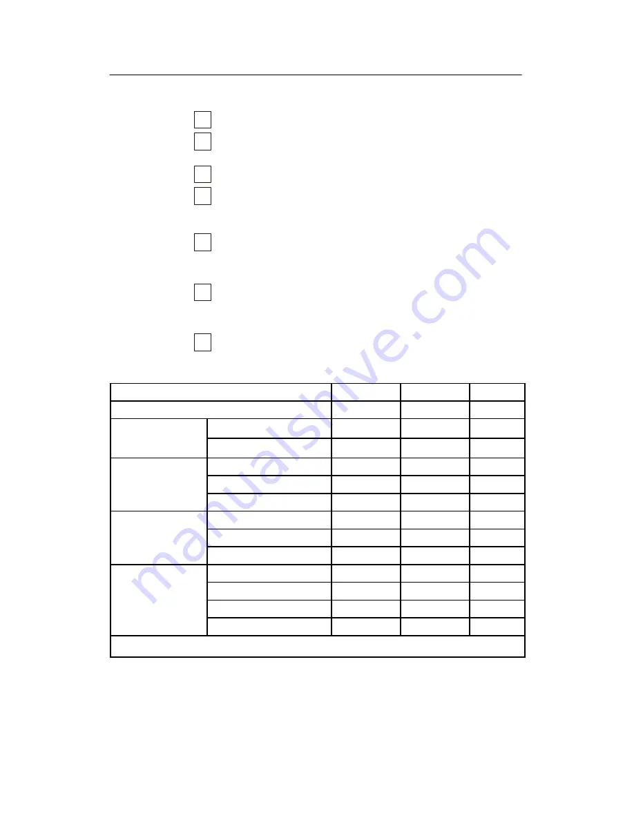
13
Enter the bearing angle, tilt angle, depth and water
temperature into the
Measurements results
table below.
→
Refer to table 4.
14
Make the requisite calculations in the
Measurements results
table.
→
The Measurement results table is shown as table 4.
15
Enter the
20 log r
and
U Hydr
. values from the
Measurements results
table into the
Source Level (SL)
table.
→
The Source Level (SL) table is shown as table 5.
Measurements/calculations
Value
Unit
Example
Measured time delay (t)
msec
5
Distance from hy-
drophone to trans-
r = 1.5xt
meter
7.5
drophone to trans-
ducer
20 log r
dB
17.5
Hydrophone voltage
in Omni
U(p--p)
volt
0.8
in Omni
U(RMS) = U(p--p)/2/
√
2
volt
0.28
U Hydr = 20 log U(RMS)
dB//1V
--11.0
Hydrophone voltage U(p--p)
volt
1.6
in 11 degrees
U(RMS) = U(p--p)/2/
√
2
volt
0.57
U Hydr = 20 log U(RMS)
dB//1V
--4.9
General information Bearing (
°
Stb/Port)
°
--36
Tilt angle
°
0
Depth below keel
meter
3
Water temperature
°
C
18
Table 4 Measurements results
Summary of Contents for Simrad SP70
Page 2: ......
Page 14: ...Simrad SP70 X 851 164336 D This page is intentionally left blank...
Page 62: ...Simrad SP70 46 851 164336 D Figure 13 Mounting the Transceiver Unit CD3110A...
Page 226: ...Simrad SP70 210 851 164336 D Party Date Signature Party Date Signature Party Date Signature...
Page 227: ......
Page 229: ......


