


974-25007001/2.0
SL 30/35 Hull Sonar Operators Manual
Page 6.8
Installation, Start-Up and Test
Kongsberg Simrad Mesotech Ltd.
Port Coquitlam, BC - Canada
pad is provided on the tank flange and a shaft clamp retainer is included. To mount
the hoist unit just insert the lower and upper locating pins and hair pin clip to secure
the ram in the proper location.
Note:
The vent cap must be installed on the oil reservoir to insure proper operation.
A Ram guide is also provided to ensure proper Ram alignment. The Power and
Upper/Lower limit switch connections must be made in the transceiver unit. A one-
meter interconnection cable and crimp-on terminal lug are supplied with the hoist
unit.
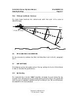
6.3.4 Mounting the Motion Sensor
The SL 35 roll and pitch angles motion sensor can be mounted mid-ship, away from
areas subject to water splash. The ambient temperature should not exceed 50
degrees Celsius. Orient the FORE mark on the unit toward the ship’s bow and
mount the unit level to within 5 degrees in all directions. See paragraph. 6.6.11, for
calibration procedure.
Note:
10 meters of interconnection cable from the motion sensor to the transceiver
unit is standard supplied.
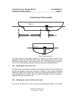
6.3.5 Mounting the Tank (Trunk) Unit
The owner and the dockyard, in deciding the location for the hull unit, must conclude
general mounting considerations. When deciding on the proper location, the
following points must be taken in to account:
•
Noise and air bubbles will affect the performance (bow plane)
•
Propeller noise (cavitation)
•
Cruising
noise
•
Acoustic
interference
•
Electrical
interference
The location must take into account the interference from other sonar or sounding
equipment. The hull unit must be at least 3.0 meters away from other transducers or
sounding equipment, to minimize interference.
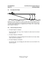
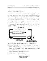
An obstacle in the fore direction will not only cause a shadow zone, but could also
aerate the water, resulting in poor sonar performance. Be sure to locate the hull unit
well away from any obstacle in the fore direction. A typical mounting method is
shown in the outline drawing provided in Part 8
“Attachments and Drawings”
for
detailed information.
Summary of Contents for SL 30
Page 1: ...SL 30 35 HULL SONAR OPERATORS MANUAL 974 25007001 Issue 2 0 September 2003...
Page 2: ......
Page 207: ......
Page 208: ......
Page 209: ......
Page 210: ......
Page 211: ......
Page 212: ......
Page 213: ......
Page 214: ......
Page 215: ......
Page 216: ......
Page 217: ......
Page 218: ......
Page 219: ......
Page 220: ......
Page 221: ......
Page 222: ......
Page 223: ......
Page 224: ......


