
974-25007001/2.0
SL 30/35 Hull Sonar Operators Manual
Page 6.10
Installation, Start-Up and Test
Kongsberg Simrad Mesotech Ltd.
Port Coquitlam, BC - Canada
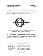
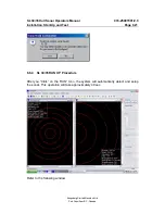
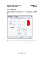
6.4.2 Tank Flange and Shaft Prepping
The tank flange comes from the factory with the shaft bearing, grease, shaft seal
and scraper installed at the factory. All tank flanges are serialized and pressure
tested. Great care must be taken not to damage the shaft seals and the flange
gasket surface during the installation.
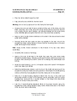
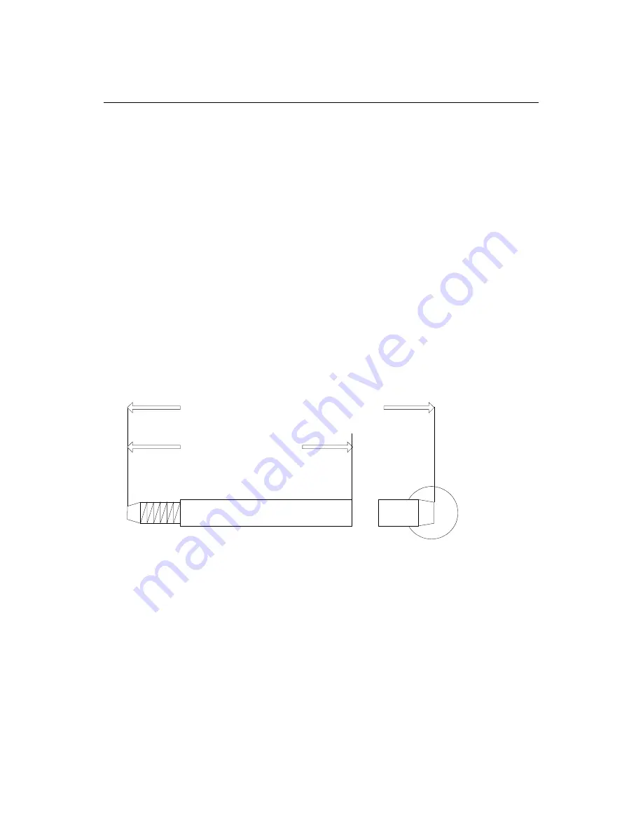
Calculate the necessary length of the main shaft from the length of the retraction
tank and cut off the extra length if necessary. If you have to cut the shaft, refer to the
shaft drawing located in Part 8 for the proper cutting procedure. If you do not follow
the proper procedure, you will damage the shaft seals and shaft scraper when you
pass the shaft through the main shaft bearing assembly.
See Part 8
“Attachments and Drawings”
for the tank flange and shaft cutting
detailed specification.
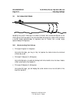
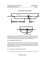
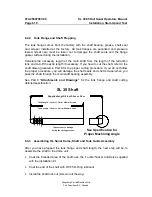
See Specification for
Proper Machining Angle
SL 35 Shaft
Tank Length - 30cm + 1.3m for 400mm Stroke
Tank Length - 30cm + 1.0m for 250mm Stroke
Supplied length: 2.4m 3.0m or 3.6m
Take care not to damage
during the cutting process
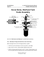
6.4.3 Assembling the Sonar Dome, Shaft and Tank Guide Assembly
After you have prepped the tank flange and shaft length, the next step will be to
assemble the shaft to the dome unit.
•
Coat the threaded area of the shaft; use the “Loctite” Nickel Anti-Seize supplied
with the installation kit
•
Coat the end of the shaft with DC 55 O-Ring lubricant
•
Install the shaft lock nut (screw in all the way)
Summary of Contents for SL 30
Page 1: ...SL 30 35 HULL SONAR OPERATORS MANUAL 974 25007001 Issue 2 0 September 2003...
Page 2: ......
Page 207: ......
Page 208: ......
Page 209: ......
Page 210: ......
Page 211: ......
Page 212: ......
Page 213: ......
Page 214: ......
Page 215: ......
Page 216: ......
Page 217: ......
Page 218: ......
Page 219: ......
Page 220: ......
Page 221: ......
Page 222: ......
Page 223: ......
Page 224: ......


