150
381295/B
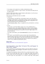
trigger pulse, the offset voltage does not have any significance. Even small variations
(flutter) over and below 0 VDC will not trigger the interface.
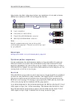
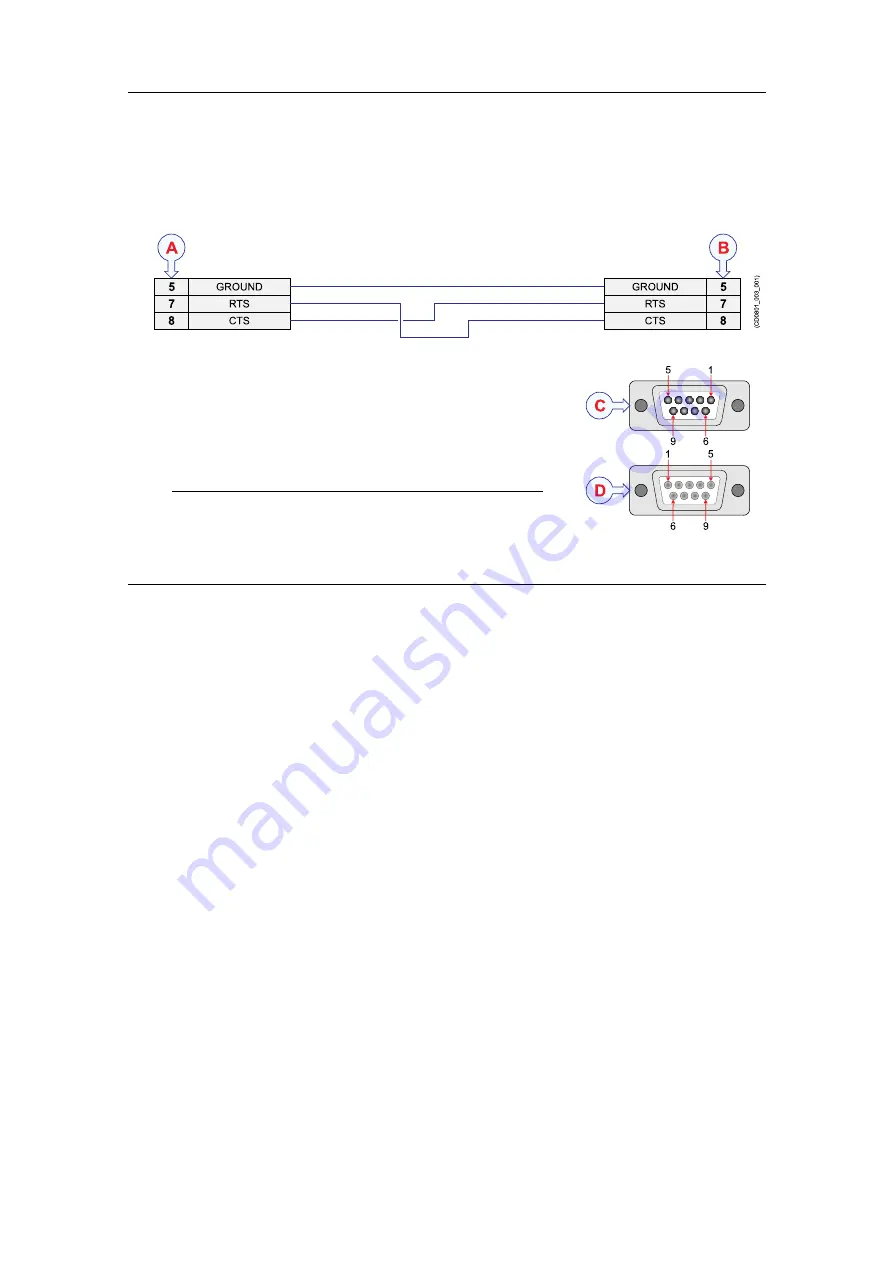
A
Local connection
B
Connection on remote device
C
Female 9-pin D-Subminiature connector
D
Male 9-pin D-Subminiature connector
Note
RS-422 communication ports can not be used for
synchronization purposes. The port you wish to use must
be set to RS-232.
Related topics
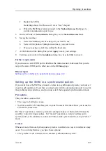
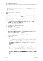
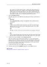
Setting up the SN90 in a synchronized system, page 148
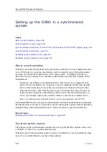
Synchronization sequences
In many applications, the synchronisation interface is based on an RS-232 serial port.
When you connect two systems for synchronisation using Clear to Send (CTS) and
Request to Send (RTS), one system must set up as a "Master" and the other as a "Slave".
When the SN90 is "Master" in a system, the synchronization can either take place in
Free
running
mode, or in
Wait for slave
mode.
Slave
mode
When the SN90 is set up in
Slave
mode, it must receive a trigger signal from a peripheral
system every time the SN90 is going to transmit. This trigger signal is connected to a
serial port on the Processor Unit, and the
Clear To Send (CTS)
pin is used to give the
SN90 an "event" message. The message is processed by the SN90 software, and it will
(if the previous ping has been finished) start the ping sequence.
As an acknowledgement to the synchronization trigger, the SN90 sets the
Ready To Send
(RTS)
signal to a logic "low" before transmitting. This indicates that the SN90 is "busy".
Once the transmission and reception sequence ends, the SN90 sets the
Ready To Send
(RTS)
signal to a logic "high" to indicate that it is ready for the next ping.
Simrad SN90 Operator Manual
Summary of Contents for SN90
Page 2: ......
Page 186: ... 2020 Kongsberg Maritime ...
Page 187: ......
Page 188: ...Simrad SN90 Purse Seine and Trawling sonar Operator Manual ...


