
9. Replace the fascia
Reattach and screw the fascia onto the unit. Replace the plastic screw
covers.
Note:
If it is necessary to run the wiring on the outside of the wall, use
a suitable conduit and fixings to properly locate and hold the wiring
used.
7. Fit one end of the duct to the fan outlet, and fix with duct clip.
Note:
Keep the route as straight and tight as possible.
USE
Our bathroom heater uses a ceramic PTC element as a source of heat.
It also combines the functions of exhaust and light.
1. Power
‘POWER’ button On/Off
Switch on the ‘POWER’ button to operate the unit.
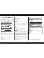
bathroom heater
spring clip
ceiling
ceiling joist
100
100
220mm
100mm minimum clearance
is required near all ceiling joists
8. Position the housing into the hole
Choosing the best direction to put the housing into the hole in
accordance with the position of the fan outlet. Pull in the installation
clips in the sliders before inserting the housing into the hole to avoid
damaging the plaster. Release clips in the sliders and use screws to
fasten the unit onto the ceiling.
Note:
Try to keep the excess wire away from the housing.
This warranty does not cover damages or loss caused by:
1) Any consequential losses arising from incorrect installation or
operation or maintenance of this product.
2) Any consequential losses arising from incorrect wiring of this prod-
uct.
3) Any modifications or changes made to the unit, other than those
recommended by the Manufacturer.
WARRANTY
The unit is warranted against defects in manufacturing and
workmanship for a period of 5 years. The warranty does not extend
installation of the unit or any associated wiring or any damage
caused by installation or wiring.
The installation must be conducted by a licensed electrician and a
suitable certificate of safety is to be issued by the electrician who
installed the unit. Warranty claims will be voided unless a certificate
of safety can be produced when required, prior to service or repair.
MAINTENANCE
Clean
1) Shut off the power before cleaning.
2) Wipe the fascia with care using a soft damp cloth.
3) Allow to dry thoroughly before switching on.
Note:
Ensure the unit is cool enough to touch before handling.
Note:
Do not switch on/off frequently when in use. Shut off the power
if in long vacancy.
3. Exhaust
‘FAN/HEATER 1’ button
This switch will extract air from the room. When in the FAN position
there is no heating of the room.
2. Lighting
‘LIGHT’ button On/Off
This switch controls the light.
4. Heating
‘FAN/HEATER 1’ button
When this switch is in the “HEATER 1”position, the heater unit will be
activated.
When the “HEATER 1” is turned on, half heating is applied to the room.
When the “HEATER 2” is also turned on, full heating is applied to the
room. When operating the heater there is no extraction.
MAIN TECHNICAL PARAMETERS
LIST OF PARTS
Operation unit
Installation instruction & hole-cutting template
1 piece
1 piece
Alluminum ducting 3.0m
1 piece
Duct clip
Switch
1 piece
2 piece
Egg-crate external grille
1 set
Model Number
Rated Voltage
Rated Frequency
Rated Power
220V-240V
50Hz
2250W
Please use this card as hole cutting template 420mm×275mm.
Read and save these instructions!
INSTALLATION INSTRUCTIONS AND HOLE-CUTTING TEMPLATE
We reserve the rights to revise these instructions without any prior notice.
For warranty purposes fill out the following details and save with proof of purchase.
This information must be submitted in the unlikely event that this product fails.*
MODEL NO.:
FAN5875
Purchased from:
Date of purchase:
*All warranty claims must be submitted through returns@simx.co.nz
FAN5875


