E Q U O B O X R T U - M o d B u s
–
U s e r G u i d e R e v . 2 . 2
S I N A P S I S . r . l . |
V i a d e l l e Q u e r c e 1 1 / 1 3 - 0 6 0 8 3 B A S T I A U M B R A ( P G )
–
I t a l y
T . + 3 9
0 7 5 8 0 1 1 6 0 4
- F . + 3 9
0 7 5 8 0 1 4 6 0 2 |
w w w . s i n a p s i t e c h . i t
i n f o @ s i n a p s i t e c h . i t
12
5.7
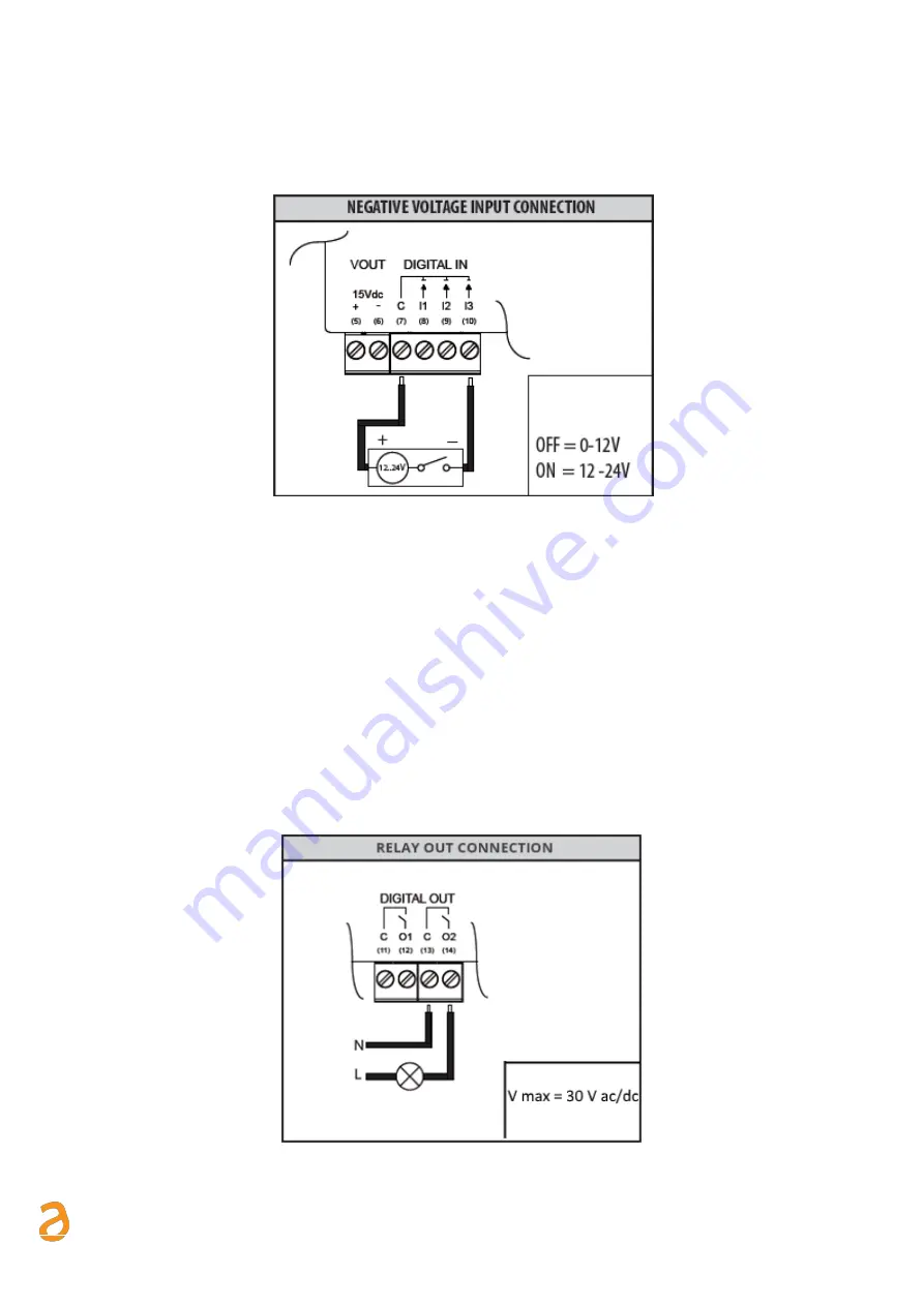
Connecting the digital inputs to negative voltage contacts
Follow the instructions below to connect the digital inputs to the device with negative voltage (in the event of
closed contacts) and voltage free contacts (in the event of open contact):
Figure 8 - Negative voltage digital input connection
•
Connect the common pole (positive) of the contact to the common terminal (7) of the device
•
Connect the negative pole of the contact to terminal (8)/(9)/(10) for inputs I1/I2/I3
When the voltage at the ends of the connected input
–
for example between (7) and (10)
–
ranges between 0V
and 12V, the RTU input is considered open (OFF). When the voltage value ranges between 12V and 24V, it is
considered closed (ON).
5.8
Digital output connection
The RTU is equipped with two relays that can be used as digital outputs. You can connect a load to them or
use them to activate other systems. Outputs O1 and O2 can be controlled both remotely and via web server
(Ref. Chapter 15). For connection to electrical loads follow the model in Figure 9 and the maximum values for
each relay shown below:
- 5A@30Vdc (Resistive Load)
- 2A@30Vdc (Inductive Load cosfi=0.4; L/R=7ms)
Figure 9 - Digital output connection


