background image

15

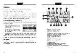
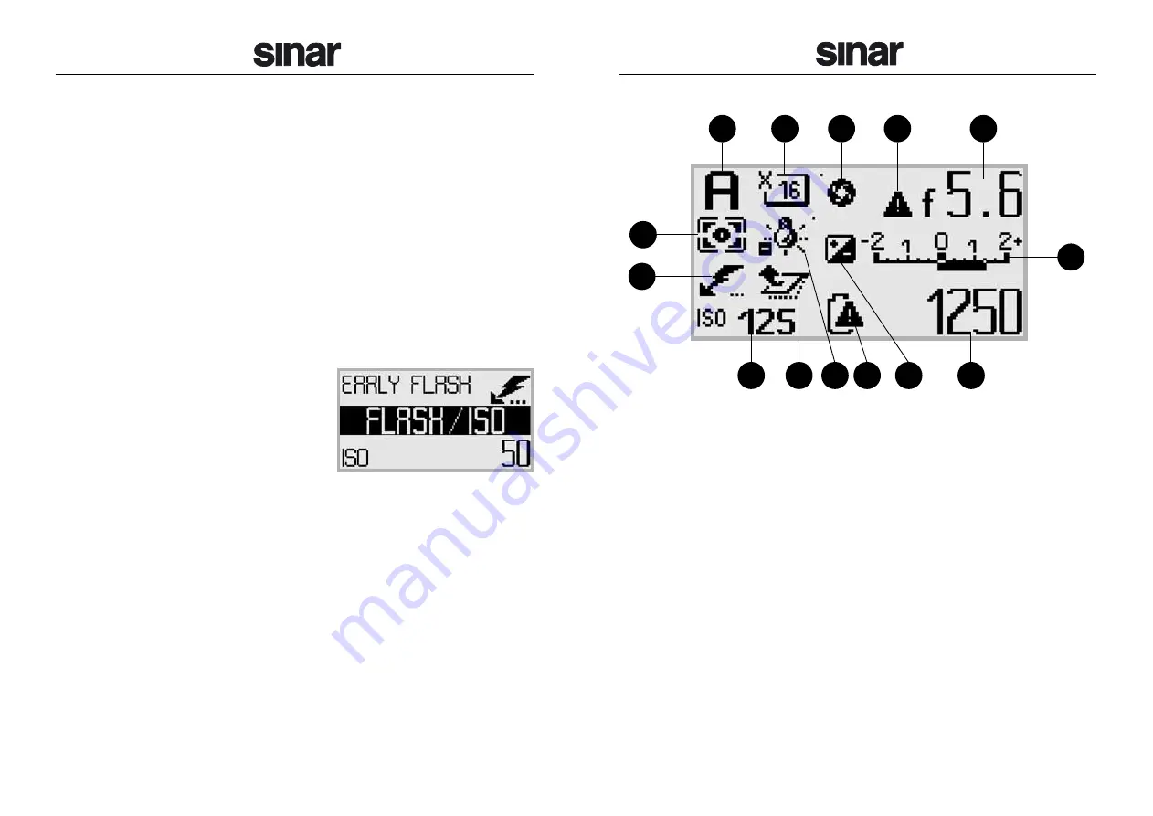
Diagram 12: Display overview

1. Selected program mode
2. Selected capture mode
3. Stopped down to working aperture/focus mode
4. Aperture control not coupled with lens
5. Selected working aperture
6. Type of exposure metering
7. Flash mode
8. Light balance / Exposure value
9. Selected sensitivity in ISO

10. Status of the shutter/mirror
11. White balance
12. State of charge/warning of the battery
13. Exposure correction activated
14. Selected exposure time in 

1

/

x

seconds resp. in 

seconds x

"

Display

The display on the Sinar m camera has the following modes:

Display of All the Relevant Settings

When the camera is ready for an exposure, all the settings relevant to
that exposure that are supported by attached modules are displayed.
Illustration no. 12 on page 15 shows which camera functions will be indi-
cated in a particular location within the display. The symbols change in
conformity with the status of the corresponding function.

Setting the Camera Parameters

As soon as Switches 2, 3 and 4 are actuated, a display divided into three
sections will appear:

In the center, the respective over-
all menu title of the operation lev-
el is displayed.

The parameters indicated above
the title can be varied by turning
the Front Dial.

The parameters indicated below the title can be varied by turning the
Rear Dial (also see chapter 

Menu Structure of the Sinar m on page 16).

Notice:

Some of the settings exclude each other mutually or are de-

pending one from another. Accordingly the options available may vary.

Messages

Error reports, warnings and notes regarding unusual operating situa-
tions, such as “Busy” or “Operation locked” etc., are also communicated
by this display.

14

1

9

6

10 11 12

13

14

2

3

4

5

7

8

Summary of Contents for 493.03.000

Page 1: ...operation Before you use your Sinarm camera for the first time please read this in struction manual carefully It will help you to use the camera correctly thus avoiding difficulties that might arise...

Page 2: ...l Contacts Jack for Hand Release 12V Power Supply Socket Display Diagram 1 Sinar m rear view D Light Gate El Contacts Locking Slider left Locking Slider right Focal Plane Shutter X Sync Socket Eylets...

Page 3: ...ts 2 Sinarm on a Sinarp3 3 Configurations 3 Set Up 5 Sinarm 7 Configurations 7 Set Up 9 Operation 11 On Off Switch 11 Shutter Release Button 11 Menu Dials Scrolling Wheels 12 Rocker Switches 12 Flash...

Page 4: ...ne 35mm or medium format camera see also the example configurations diagrams 4 to 11 Requirements In order to work with the Sinar m you need in addition to the accessories listed in the corresponding...

Page 5: ...f the Sinarm and push the Sinarback towards the Sinar m until the snap lock slid er snaps in automatically Notice Check if the adapter plate is locked in place correctly 8 Mount the bellows on the fro...

Page 6: ...on your flashlight unit When using a Sinarback with fiber optics interface and a PowerOptics Master cable this cable can also be plugged in the respective socket of the PCI Board 2 too 17 Start the M...

Page 7: ...used 6 Mount the mirror module or the lens module on the front of the Sinar m and lock it by pushing both locking sliders inwards Check if the mir ror module or the lens module is locked in position c...

Page 8: ...ave activated and the displayed setting will be confirmed Every time the shutter release button is actuated an acoustic signal will resound when the function Acoustic Signal is activated 11 When using...

Page 9: ...the display and the setting of the working aperture The Rear Dial allows the selection of functions listed in the lower line of the display and the setting of the exposure time Please check the tables...

Page 10: ...on page 15 shows which camera functions will be indi cated in a particular location within the display The symbols change in conformity with the status of the corresponding function Setting the Camer...

Page 11: ...on is not available with Sinar CaptureShop version 4 x This function is not available with Sinar CaptureShop version 4 x Switch 2 PRGM Center of Display Top of Display Bottom of Display Front Dial Rea...

Page 12: ...lay Top of Display Bottom of Display Front Dial Rear Dial Switch 4 ISO Center of Display Top of Display Bottom of Display Front Dial Rear Dial continued on next page This function is not avail able wi...

Page 13: ...blades or hinder their movement char acteristics which could result in the reduction of their operating relia bility Whenever you are not using the Sinarm camera we recommend that you always store it...

Page 14: ...Digital CAB Sinaron Digital CMV Hasselblad V System Nikon further adaptations are in preparation Shutter Type Electronically controlled vertically moving focal plane shutter Shutter Size 56 42mm appro...

Reviews: