background image

C

ONTENT


Sinar arTec Operating Instruction V 1.00 

27


5.3  Using a Shading Image in the Sinar eXposure™ Software 

5.3.1 Preparation 

You have already installed the Sinar eXposure™ Software Version 6.1.1 or higher on your computer and you 
are already familiar with its current functions. The section that follows supplements the integrated help function 
of the Sinar eXposure™ software. 
 
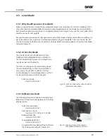
In order to make the shading function more readily accessible, it is worthwhile to add it to the toolbar: In the 
"View" menu, go to the "Toolbar" and select "Customize toolbar...". 


Fig. 44:  Add the Shading function to the Toolbar 

of the Sinar eXposure™ software 


There you will find an ample selection of function icons. Select the “Shading Mode“ icon and drag-and-drop it 
into the toolbar. As soon as you drag the icon into the toolbar, a place is opened for the new function. 

5.3.2  Defining the Shading file and assigning it to the images 

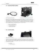
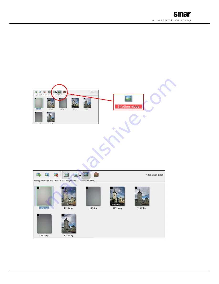
When you have your pictures in front of you on a Contact sheet, you can now call up the "Shading Mode". You 
will immediately see a small black square in the upper left corner of every image. That square is a control field 
that refers to the Shading files. 


Fig. 45: Contact sheet in the Sinar eXposure™ software

:

 Activating the Shading mode 


Now mark all the images that you made with the Shading Diffusor by clicking on the small black square of 
every Shading file. 
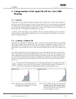
As soon as a shading data file has been defined, it will be applied to all the images that follow, until the next 
Shading file comes up. 

Summary of Contents for arTec

Page 1: ...Sinar arTec _____________________________________________________________________ The Camera System for Digital Architectural Photography Operating Instructions...

Page 2: ...e subject to the intellectual property rights and the personal rights of the respective country Any other use than personal private is only allowed in accordance with the intellec tual property right...

Page 3: ...a Digital back with a Revolving adapter on Sinar arTec Hy6 9 2 5 2 Changing the format on a Digital back with a Conventional adapter on Sinar arTec Hy6 9 2 5 3 Changing the format on a Digital back mo...

Page 4: ...s the Exposure 21 3 4 1 Image settings 21 3 4 2 Changing between Viewing position and Exposure position 21 4 ACCESSORIES FOR THE SINAR ARTEC CAMERA 22 4 1 Lenses 22 4 2 Lens Adapter Rings 22 4 3 White...

Page 5: ...mage precisely on the focusing screen and the exposure position is then used for making the actual photograph To change from the viewing position to the exposure position a slider is moved to the righ...

Page 6: ...are supplied with your version of the camera is complete and undamaged If anything is missing or if something is damaged contact your supplier immediately 1 3 1 Sinar arTec Hy6 Item no 493 23 000 wit...

Page 7: ...Case 02 1180x Operating Instructions Sinar arTec as a PDF file on a CD Fig 3 Empty Sinar arTec System Case in which the whole scope of delivery and also lenses of choice are stored 1 3 4 Sinar arTec e...

Page 8: ...digital back and the flexible focusing magnifier Fig 4b Front view of the Sinar arTec showing the lens the Rod holder and an Accessory shoe A Sinar arTec camera body B Sinar Revolving Adapter C Digita...

Page 9: ...5 Micro drive for horizontal shifts 6 Locking lever for the Horizontal micro drive 7 Attachment position for digital backs 8 Locking slider for digital back left right Sinar arTec Hy6 9 Combined Fres...

Page 10: ...g pin for rotating swinging the Lens carrier frame 25 Locking lever for rotations swings of the Lens carrier frame Fig 7 All important operating elements are conveniently accessible to the photographe...

Page 11: ...a digital back to the Sinar arTec Hy6 camera 2 3 1 Attaching a Digital back 5 Remove the left protective cover by shifting the two Locking latches 8 upwards until they are le vel with the line at the...

Page 12: ...ve cover that is held in place by magnets 51 by grasping it at the top and then simply pull it away 2 Place the digital back after first having attached the corresponding adapter plate to that back on...

Page 13: ...n Sinar arTec Hy6 When a camera adapter other than the Sinar Revolving Adapter is used on a Sinar arTec Hy6 camera the digital back has to be detached from the camera and rotated by 90 for changing th...

Page 14: ...swung Otherwise the bundle of light rays would be blocked by the Fresnel lens that is located under the focusing screen Thanks to this flexibility the focusing screen can still be viewed all the way...

Page 15: ...2 8 1 Features The metallic Format mask of the Sinar arTec camera item no 493 23 504 has an opening that corresponds to the size of the sensor of the Sinarback eMotion 54 Sinarback eMotion 75 or the S...

Page 16: ...lso see figure 17 Make sure that the lens is installed securely by grasping it in a controlled manner Fig 15 Attaching the lens Fig 16 Latching the lens board Fig 17 The lens latching slider Make sure...

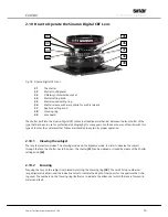
Page 17: ...those who are not familiar with this type of shutter the comments that follow are intended to explain its proper operation 2 10 1 Viewing the subject The lens features two modes The Viewing mode and...

Page 18: ...king aperture is set by means of the Aperture setting knob 37 The range of f stops may vary for dif ferent lenses For the best possible light transmission the subject should be viewed with the shutter...

Page 19: ...t 44 Firewire socket 45 Trigger in socket 46 Winder out socket For proper operation and the handling of your digital back please read the operating instructions supplied with the respective digital ba...

Page 20: ...ter 2 12 3 or put the Cover slide back into the roll film magazine so that you can remove it from the camera see chapter 2 4 Please note that the double exposure prevention feature does not work when...

Page 21: ...igure 23 5 Micro drive for horizontal shifts 15 Micro drive for vertical shifts 23 Micro drive for tilts 25 Locking lever for rotations swings Fig 23 All the important operating elements are arranged...

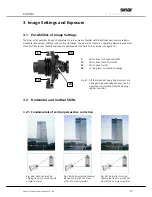
Page 22: ...e uses the Micro drive for vertical shifts 15 also see figure 24 and figure 5 until the entire building is included in the image To perform this shift first loosen the Locking lever 16 and then use th...

Page 23: ...used frequently for interior photographs with the purpose of reproducing vertical lines correctly meaning parallel and to prevent the camera from becoming visible in the image for instance on a mirror...

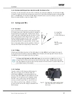
Page 24: ...long a common line B Image Plane O Lens Plane S Plane of Sharpness Fig 28 The Scheimpflug Principle 3 3 2 Tilting Tilting is performed directly by means of the self locking micro drive 23 also see the...

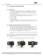
Page 25: ...ween Viewing position and Exposure position 7 When you have finished composing the picture and you made all the settings in the Viewing posi tion see figure 30a shift the camera Slider into the Exposu...

Page 26: ...81 055 445 87 103 Sinaron Digital 4 5 45 CEF 4 5 32 95 100 0 6 m M67 547 81 055 445 87 105 Sinaron Digital 4 5 55 CEF 4 5 32 93 120 0 9 m M67 547 81 055 445 87 164 Sinaron Digital HR 4 0 60 CEF 4 0 32...

Page 27: ...r arTec Hy6 493 23 000 and the Sinar arTec HB V 493 23 001 cameras This accessory is also available separately as Item Number 551 43 097 4 4 Filter Rod Holder The optional Filter Rod Holder see figure...

Page 28: ...ec Lens Shade The one piece Artec Lens Shade consists of two folding and two sliding panels and it is affixed to the Lens Adapter Ring by means of a manual fasten ing screws also see Chapter 4 2 The A...

Page 29: ...t path at any time Its positioning on the Filter Rod is freely adjust able The diameter of the Sinar Circular polarizing Filter is 110 mm 4 inches Swiveling Circular Polarizing Filter Item No 546 31 0...

Page 30: ...has been moved too far the edge of the image circle will appear in the picture Such artifacts are to be avoided of course as they cannot be eliminated even by means of the Shading correc tion When all...

Page 31: ...an ample selection of function icons Select the Shading Mode icon and drag and drop it into the toolbar As soon as you drag the icon into the toolbar a place is opened for the new function 5 3 2 Defi...

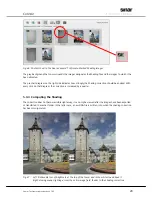
Page 32: ...be applied With every click on that diagram the correction is increased by a quarter 5 3 3 Computing the Shading The correction does not become visible right away it can only be viewed after the image...

Reviews: