background image


ADJUSTMENTS 


Each PG-239 machine places a grommet model and a washer, although other grommet dimensions 
may be placed by replacing the corresponding parts. This replacement is quick and simple. In order 
to fix a different grommet model a whole new raceway is needed together with the appropriate set of 
dies. 
 
With the machine unplugged: 
 
1- Remove the stripper plate spring nº 237 from the raceway spring nut nº 238 which holds it in 
place. 
2- Loosen both mounting screws nº 244 which are holding the front hopper box mounting bracket nº 
240. 
3- Use both hands for holding the grommet hopper box housing nº 242 and the grommet hopper box 
bottom plate nº 241and begin to push upwards (with slight clockwise rotations) in order to remove 
the whole raceway from the front hopper box mounting bracket nº 240. 
 
The  whole set of dies or some of its parts (part nº 217, 218, 219 y 229) will have to be replaced 
according to the different grommet models. 
The dealer that sold you this machine or directly Sinclair will let you know about the parts that 
should be replaced. If no part of the set of dies needs to be replaced, continue at point 8. 
Changing the whole set of dies: 
4- Pull upwardsthe ring compensator nº 233C by moving the compensator base latch nº 196 that 
holds it. 
5- Unscrew the top die nº 217, remove the top set spindle nº 218 and the top set spindle spring nº 229     
, which are inside the top die. Unscrew the bottom die nº 219. 
6- Replace the set of dies corresponding to the new grommet size, in the same order in which the 
other parts were removed. Firstly the top die nº 217       with the top set spindle nº 218 and the top set 
spindle spring nº 229 and then remove the bottom die nº 219. 
7- Replace the ring compensator nº 233C  around the bottom die nº 219, fit the compensator base 
latch nº 196 into the ring compensator groove nº 233C in order to hold it in place. 
 
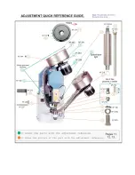
Before starting the machine, it is necessary to adjust the tightness of your setting (Point 4.2. 
Adjusting the tightness of setting, change of dies; page 12). 
 
8- Fit the new grommet raceway into the front hopper box mounting bracket nº 240 while manually 
rotating it back and forth, so that the driving stem nº 243 which is in the lower part, gets into the 
hopper box motor spin axis nº 239. 
9- Tighten both 6 allen screws nº 244 for holding the part nº 240       , 
10- Hold the stripper plate spring nº 237, which is held in place by the raceway spring nut nº 238. 
11- The lower part of the raceway where the grommet you are going to set is placed, must be on the 
same vertical line as the spindle nº 218 so the spindle can take the grommet while coming down,  
12- Adjust the tightness of setting (Point 4.2. Adjust the tightness of setting and changing dies). 
Remember you have to keep using the same washer model, you must not change it. 


Summary of Contents for Electronic Automatic Grommet PG-239

Page 1: ...Model PG 239 Electronic Automatic Grommet Operating Manual 800 624 2408 530 626 9386 Fax 530 626 5144 6686 Merchandise Way Diamond Springs Ca 95619 www sineqco com...

Page 2: ...ts about its operation Read this manual carefully to securely operate and optimize the machine s capability We urge you to follow this advice and appreciate your trust at the moment of buying the mach...

Page 3: ...e rotated by individual 24V motors The grommets that descend along the left raceway A2 are held by a small finger which stops them from falling Lower horizontal guides hold the washers descending alon...

Page 4: ...carry packaging which is sufficient to avoid knocking or scraping any of its components We advise that wooden packaging in box or cage form should always be used always with adequate protection and th...

Page 5: ...of the machine must always be carried out with the machine disconnected from the mains power supply Do not remove from the machine any parts which protect the user from possible accidents or adhesive...

Page 6: ...THE ADJUSTMENTS SECTION OF MANUAL SINCLAIR EQUIPMENT will accept no responsibility arising from the use of this machine in any way different from that which is described in this instruction manual SE...

Page 7: ...s or disconnects the two 24V motors that make the grommets and washers rotate in the deposits 6 Washer detector detects the flow of washers in the railing When selected with the position 0 it does not...

Page 8: ...y must be moved back and the top and bottom dies parts n 217 218 219 and 229 must be replaced by other parts specific to this task THIS MACHINE MUST NOT BE USED FOR ANY FUNCTION OTHER THAN THAT FOR WH...

Page 9: ...n 217 remove the top set spindle n 218 and the top set spindle spring n 229 which are inside the top die Unscrew the bottom die n 219 6 Replace the set of dies corresponding to the new grommet size i...

Page 10: ...n rotate the bottom die holder part n 220 until the bottom die part n 219 barely touches the top set spindle part n 218 Secure the bottom die holder part n 220 through nut The pressure of the spindle...

Page 11: ...ets and washers the machine may come with a little air pipe attached to the washer raceway which blows the washer down onto their right position by means of an air compressor For placing grommets and...

Page 12: ......

Page 13: ...a week If the machine is going to go for a long period of time without use it will be necessary to do a general cleaning and greasing in the indicated spots disconnecting it from the compressor or fr...

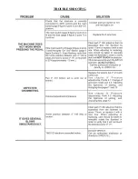
Page 14: ...TROUBLESHOOTING...

Page 15: ......

Page 16: ......

Page 17: ...pieces of material that are left after the grommeting action This pipe allows the operator to work more comfortably These protection devices are tightly held through screws that prevent them from beco...

Page 18: ...4 PGR239154 Laser Pointer Threaded Support 204 PGR239204 Motor Mount Bolts Nuts Washers 4 155 PGR239155 Laser Pointer 206 PGR239206 Machine House Bolts Nuts Washers 4 155c PGR239155C Laser Pointer Set...

Page 19: ...ger 227 PGR239227 Raceway Cam 183CA PGR239183CA Upper part of washer compensator axle 228 PGR239228 Raceway Cam Bracket 184CA PGR239184CA Lower part of washer compensator axle 230 PGR239230 Driving St...

Page 20: ...g Guard Bracket 226 PGR239226 Bottom Plunger Guide Pin 190 PGR239190 Plunger 227 PGR239227 Raceway Cam 202 PGR239202 Plunger Housing 228 PGR239228 Raceway Cam Bracket 215 PGR239215 Upper Guide Collar...

Page 21: ...R239208 Crankshaft Key Way 209 PGR239209 Front Crankshaft Key Way 210 PGR239210 Front Washer 211 PGR239211 Front Crankshaft Nut 212 PGR239212 Collar 213 PGR239213 Collar Insert 214 PGR239214 Plunger C...

Page 22: ...6 PGR239246 Brush Spacer 247 PGR239247 Acrylic Box Cover 251 PGR239251 Knob for opening the hopper box cover 253 PGR239253 Upper box bearing 270 PGR239270 Mounting studs 291 PGR239291 Knob washer 310...

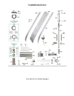
Page 23: ...WASHERS RACEWAY See parts list on following page...

Page 24: ...k stud 233C PGR239233c Ring compensator set 300 PGR239300 Slide stud screw 234 PGR239234 Base Washer 301 PGR239301 Long slide track rail 235 PGR239235 Screw for base 302 PGR239302 Short slide track ra...

Page 25: ...5 PGR239255 Front Hppr lwr brkt 268 PGR239268 Finger cut off 256 PGR239256 Mounting studs 269 PGR239269 Hopper box assy screws 257 PGR239257 Mounting stud nut 271 PGR239271 Raceway strip spacers 258 P...

Page 26: ...ic box cover 240 PGR239240 Front hopper box mntg brkt 251 PGR239251 Knob for opening hopper cover 241 PGR239241 Hopper box bottom plate 253 PGR239253 Upper box bearing 242 PGR239242 Hopper box housing...

Page 27: ......

Page 28: ......

Page 29: ...NOTES...

Reviews: