1. DESCRIPTION OF THE MACHINE AND ITS OPERATION.
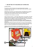
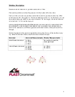
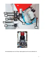
(See figure below)
The machine consists of the head, air hoses and pneumatic foot pedal.
The moving parts in the machine are located inside the head (pneumatic cylinder,
manometer, axles, dies, etc.).
After placing the machine in its permanent location, without fitting the air hosepipe
into the mouth of the compressor, verify that it has not suffered any blow or
breakage while being transported and that it has not any loose parts.
The operation of the machine is very simple:
When pressing the pedal “C” a pneumatic safety cylinder “B” is activated. The safety
cylinder causes the ring guard “E” to descend right to the point where it can check
that there are not any fingers or hands in the grommeting area “D” and activates the
micro end of race which sets the pneumatic cylinder “A” in motion.
The pneumatic cylinder “A” causes the vertical axles to descend. Attached to the
lower part of the vertical axles are the top set spindle and the top die that does the
grommeting.
The aim of the downward movement of the axles is to cause the top-set spindle to
punch out a hole in the material and to set the grommet situated in the grommeting
area “D”, by means of the pressure that the top-die puts on the bottom die.
3
After this cycle the machine returns to its starting position ready for a new
application as soon as you place the grommet and the washer and press the pedal
“C”.
C
A
B
D
E
Summary of Contents for Pneumatic Grommet Machine PG-21
Page 20: ...20...
Page 21: ...21 NOTES...


