16
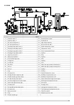
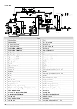
Key components:
1.
Compressor
Maintains pressure differential between high and low pressure sides of the refrigerant system.
2.
Fan:
Ventilates the air side heat exchanger.
3.
Oil separator:
Separates oil from gas refrigerant pumped out of the compressor and quickly returns it to the compressor. Separation
efficiency is up to 99%.
4.
Vapor-liquid separator:
Stores liquid refrigerant to protect the compressor from liquid hammering.
5.
Electronic expansion valve:
Controls refrigerant flow and reduces refrigerant pressure.
6.
Four-way valve:
Controls refrigerant flow direction. Closed in cooling mode and open in heating mode. When closed, the air side heat
exchanger functions as a condenser and water side heat exchanger functions as an evaporator; when open, the air side heat
exchanger functions as an evaporator and water side heat exchanger function as a condenser.
7.
High and low pressure switches:
Regulate refrigerant system pressure. When the refrigerant system pressure rises above the upper limit or falls below the
lower limit, the high or low pressure switches turn off, stopping the compressor.
8.
Discharge temperature switch:
Protects the compressor from abnormally high temperatures and transient spikes in temperature.
9.
Air purge valve:
Automatically removes air from the water circuit.
10.
Safety valve:
Prevents excessive water pressure by opening at 6bar and discharging water from the water circuit.
11.
Water flow switch:
Detects water flow rate to protect the compressor and water pump in the event of insufficient water flow.
12.
Pressure sensor:
Measures refrigerant system pressure.
13.
Crankcase heater:
Prevents refrigerant from mixing with compressor oil when the compressors are stopped.
14.
Water side heat exchanger electric heater:
Protects the water side heat exchanger from ice formation.
15.
Water flow switch electric heater:
Protects the water from ice formation.
16.
Plate heat exchanger(Economizer):
In cooling mode, it can improve super-cooling degree and the super-cooled refrigerant can achieve better heat exchange in
indoor side. In heating mode, the refrigerant comes from the plate heat exchanger going to the compressor can enhance
the refrigerant enthalpy and improve the heating capacity in low ambient temperature. Refrigerant volume in plate heat
exchanger is controlled according to temperature different between plate heat exchanger inlet and outlet.
17.
Pressure gauge joint (high and low pressure side):
Charges or discharges refrigerant.
18.
Capillary:
Normally return oil to the compressor.
19.
Solenoid valve SV4(oil balance):
Quickly return oil to the compressor.
20.
Solenoid valve SV5(defrost):
Multiple functions for enhancing reliability.
Summary of Contents for SCV-1400EB
Page 2: ......
Page 4: ...2...
Page 8: ...6...
Page 26: ...24...
Page 46: ...44 1 Electric Control Box Layout For SCV 750EB For SCV 1400EB...
Page 61: ...59 3 Wiring diagram 3 1 Single unit For SCV 750EB and SCV 1400EB...
Page 62: ...60 For SCV 900EB...
Page 63: ...61 For SCV 1800EB...
Page 78: ...76 5 5 E3 E4 E5 E7 Eb Ed EE EF EP EU Fb Fd Troubleshooting Digital display output...
Page 159: ......
Page 160: ...0 1 234 56 0 7 8 234 0 9 1 7 1 0 6 16 3 5 9 4 260 88 4 260 88 08 88 688 0 4 08 4 6 4A8 60 B...


