background image

20

ENGLISH

In the event of installation inside a closed housing, make sure 
that the cooling air temperature for the generator does not rise 
above standard.

The housing must be constructed so that the engine air vent in 
the housing is separate from the generator air vent especially 
if the air inlet in the hous ing has to be supplied by the cooling 
fan. What’s more, the generator air vent should be constructed 
to  prevent  damp  from  entering  by  fi tting  suit a ble  protections. 
The  housing  should  be  designed  so  that  there  is  a  minimum 
clearance of 50mm between the generator air vent and any 

fl

 at 

surface.

If 

specifi


ed


on


order,


the


generator


can


be


fi


tted

  w

ith


air


fi


lters.

i

W

A

R

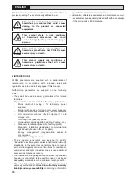
NING

!

A


drop


in


cooling


air


fl


o

or


inadequate


protection


of


the


gen


er


a


tor


can


lead


to


damage


and

/

or


malfunction


of


the

 w

indings.

The  engine  induces  quite  complex  vibrations,  including 
overtones that, when added to the generator vibrations, can 
cause substantial vibration levels damaging for the electricity 
generating  set  operation.  Therefore  it  is  es sen tial  that  the 
plant  engineer  takes  all  necessary  measures  to  ensure 
align ment and provide a fi rm base and supports in order to 
prevent vibrations from exceeding the standard.

The alternator is dimensioned in accordance with standard 
ISO 

8528

-

9

.

Dual  bearing  generators  require  a  rigid  frame  to  support 
the  engine/gen er a tor  so  that  a  good  base  is  established 
for a precise alignment. This frame should be anchored to 
the base with antivibration plugs. In order to min i mise twist 
oscillations,  it  is  advisable  to  use  a  suitably  sized 

fl

 exible 

joint.

In belt transmissions applied to dual bearing generators it is 
essential that the pulley diameters and constructions permit 
the load applied to the shaft to be centred with the length of 
the nub and not to exceed 

2

000N. For greater shaft lengths 

the acceptable loads can be requested directly to the Sincro 
Technical Offi ce.

Alignment of single bearing generators is critical because it 
may give rise to vibrations along the coupling between engine 
and  generator.  For  this  purpose  special  attention  must  be 
given to the alternator to engine as sem bly, providing a solid 
base  and  implementing  anti-vibration  plugs  to  support  the 
engine/alternator assembly.

The  terminal  box  contains  the  insulated  terminals 
for  connecting  the  line  and  neutral  and  for  the  earth 
connection.

The


neutral


is


NOT


connected


to


the


housing.

!

W

A

R

NING

!

The


generator


is


supplied

  w

ithout


a


connection


to


earth

;


to


ma

k

e


this


connection


refer


to


relevant


local


regulations.


An


in


ef


fi


cient


earth


con


nec


tion


or


safet

cut

-

out


can


cause


in

j

ur

or


death.

The generator fault currents are available on request to help 
the plant en gi neer in sizing the plant and its components.

!

W

A

R

NING

!

An


error


in


installation,


use,


maintenance


or


replacement


of


parts


can


cause


severe


in

j

ur

or


death,


not


to


mention


damage


to


the


ma


chin


er

y

.


All

 w

or

on


electrical


and

/

or


mechanical


parts


must


be


carried


out


b

a


qualifi


ed


specialist.

Summary of Contents for SK 225

Page 1: ...Manuale di Uso e Manutenzione Use and Maintenance Manual SK 225 0900242 REV 00 12 2009...

Page 2: ...iversi circuiti 10 6 4 6 Messa in marcia 10 7 ASSISTENZA E MANUTENZIONE 11 7 1 Controllo degli avvolgimenti e dello stato di isolamento 11 7 2 Controllo dei cuscinetti 11 7 3 Anomalie e rimedi 12 7 4...

Page 3: ...ntazione Usi non indicati in questa documentazione potrebbero essere fonte di danni al prodotto e fonte di pericolo La Sincro S r l declina qualsiasi responsabilit derivante dall uso improprio o diver...

Page 4: ...ortabile con cofanatura per fornitura di energia temporanea A bordo sottocoperta impiego marino previa omologazione Su veicolo commerciale trasporto su ruote refrigerazione etc Su rotaia energia ausil...

Page 5: ...ore al fine di eliminare eventuali instabilit di tensione che si dovessero manifestare Un fusibile protegge il regolatore e il generatore da eventuali sovraccarichi e o guasti Scheda AVR 5 SPECIFICHE...

Page 6: ...sostegno del motore generatore in modo da costituire una buona base per un esatto allineamento Tale telaio dovr esserevincolatoalbasamentomediantetamponiantivibranti Al fine di ridurre al minimo le o...

Page 7: ...raggio fare riferimento al punto 6 2 5 6 2 1 Montaggio forma IM B35 ATTENZIONE Prima del montaggio verificare che le sedi coniche di accoppiamento sia del generatore che del motore siano compatibili r...

Page 8: ...nessioni meccaniche si consiglia di utilizzare viti con classe di resistenza minima 8 8 Le coppie di serraggio sono riportate nella seguente tabella COPPIE DI SERRAGGIO Nm mat 8 8 Diametro di filettat...

Page 9: ...alersi degli schemi allegati al presente manuale AVVERTENZA Le eventuali modifiche al collegamento devono essere eseguite esclusivamente da personale qualificato 6 4 4 Regolazione scheda AVR AVVERTENZ...

Page 10: ...ollegamento stella serie normalmente eseguito in produzione a meno di specifiche diverse all atto dell ordine 6 4 6 Messa in marcia Prima dell avviamento del gruppo elettrogeno necessario verificare c...

Page 11: ...ti I cuscinetti sono sigillati ed esenti da manutenzione Durante la manutenzione controllare lo stato dei cuscinetti e verificare che non siano presenti perdite di grasso la durata dei cuscinetti dipe...

Page 12: ...chiesta Regolare la tensione con il potenziometro V dell AVR Settaggio sottovelocit non corretto Controllare e sistemare la sottovelocit con il potenziometro UF dell AVR Vedi 6 4 4 Regolazione della s...

Page 13: ...lungo la scarpa polare AVVERTENZA Quando viene reinserito il rotore l alternatore pu perdere il magnetismo residuo che permette l autoeccitazione Prima dell avviamento del gruppo risulta quindi necess...

Page 14: ...tto seguendo le istruzioni dei paragrafi 7 4 1 7 4 2 7 4 3 7 4 5 Riassemblaggio di componenti e gruppi di componenti Per l operazione di riassemblaggio compiere a ritroso le precedenti operazioni eseg...

Page 15: ...liente indipendentemente dalla concessione dell intervento in garanzia Curare che le macchine siano in ordine pulite Si raccomanda di restituire il materiale entro un imballo adeguato curando di prote...

Page 16: ...Wiring diagrams for different circuits 24 6 4 6 Initial start up 24 7 AFTERSALES ASSISTANCE AND MAINTENANCE 25 7 1 Control of windings and electrical insulation 25 7 2 Control of bearings 25 7 3 Trou...

Page 17: ...cted solely for the applications indicated in this manual Any use not specified in this manual may cause damage to the product and become a source of hazard Sincro S r l declines all liability arising...

Page 18: ...supplies Onboard below deck marine use after certification On commercial vehicles freight transport cold storage etc On rolling track auxiliary power On industrial vehicles earth handling hoisting etc...

Page 19: ...ND ELECTRICAL SPECIFICATIONS FOR COUPLING WITH ENGINE As an independent unit designed to be built into a electricity generating set it is impossible to apply all the signal decals on the generator dur...

Page 20: ...s established for a precise alignment This frame should be anchored to the base with antivibration plugs In order to minimise twist oscillations it is advisable to use a suitably sized flexible joint...

Page 21: ...35 CAUTION Before proceding with assembly check that the faces couplings both on generator and engine are compatible in order and perfectly clean Remove the protective grids 6 Fasten the shield 1 to t...

Page 22: ...ions provided in section 6 2 3 6 2 5 Tightening torques For mechanical connections it is recommended to use screws at least class 8 8 The tightening torques are shown in the following table TIGHTENING...

Page 23: ...ntacts are left bare it is important that this operation be carried out solely by qualified specialists in electrical plant maintenance To select the AVR settings access the control board after removi...

Page 24: ...ual there are diagrams for any connections other than the factory star series standard unless otherwise specified on order 6 4 6 Initial start up Before starting up the generating set check that all e...

Page 25: ...be blown through the alternator for at least 1 hour 7 2 Control of bearings The bearings are sealed and maintenance free During maintenance control the condition of the bearings and check that no gre...

Page 26: ...voltage is not set at desired value Adjust voltage with potentiometer V on the AVR Under frequency protecton not properly adjusted Check adjust the value of under frequency protection with the trimme...

Page 27: ...ositioned thealternator may loose the residual magnetism that enables it to self excite Before starting up the generating set the alternator will therefore have to be excited by applying a 6 12 volt c...

Page 28: ...everything following the instructions given in sections 7 4 1 7 4 2 7 4 3 7 4 5 Replacing components and component assemblies When assembling after changing a part repeat the above operations in rever...

Page 29: ...t regardless of whether warranty coverage will be claimed or not The client must make sure that the machines sent for repair are in good order clean and that the oil in the overgear system has been dr...

Page 30: ...30 SK225 Disegno esploso Exploded view Telimontagezeichung Vue eclat e Despiece...

Page 31: ...nique AVR BL4 Tarjeta electr nica AVR BL4 3008025 40 Scatola terminali Terminal box Verbindern Schachtel Bo te connecteurs Caja conectores Box 43 Morsetto isolatore M8 M8 insulator clamp Isolatorklemm...

Page 32: ...32 12 morsetti 12 wires 12 klemmen 12 bornes 12 bornes...

Page 33: ...1 U2 W2 V2 V1 W1 L3 W L2 V W2 U2 V2 W1 V1 U1 L1 U L2 V sensing 0 230 L3 W 3 3 L1 U N U1 U2 W2 V2 W1 V1 L3 W L2 V N W2 U2 V2 W1 V1 U1 L1 U L2 V sensing 0 230 L3 W 6 morsetti 6 wires 6 klemmen 6 bornes...

Page 34: ...34 12 morsetti 12 wires 12 klemmen 12 bornes 12 bornes 6 morsetti 6 wires 6 klemmen 6 bornes 6 bornes...

Page 35: ...ER ROTOR EXCITER AUX WINDING 400V 50Hz 400V 50Hz no load nominal load PHASE LINE e0 i0 en in mOhm Ohm Ohm mOhm Ohm V A V A SS 156 1 45 15 1 162 4 5 9 0 0 65 50 0 2 6 SM 120 1 61 15 1 162 4 3 MS 74 1 8...

Page 36: ...36...

Page 37: ...37...

Page 38: ...38...

Page 39: ...tive 2004 108 CE relative au rapprochement des l gislations des tats membres concernant la compatibilit lec tromagn tique La v rification de compatibilit a t effectu e conform ment aux normes suivante...

Page 40: ...222 www sogaenergyteam com sales sincro sogaenergyteam com Sincro srl si riserva il diritto di modificare i dati per aggiornare o migliorare i propri prodotti senza alcun preavviso Sincro srl reserves...

Reviews: