15
4 Wiring
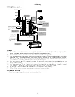
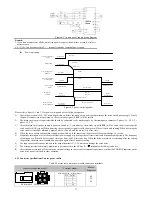
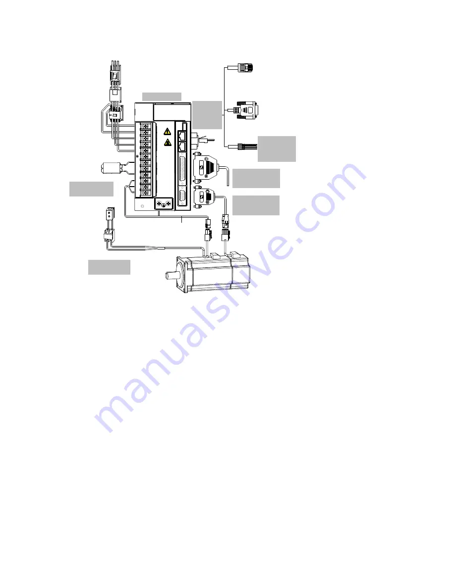
4.1 Peripheral connection
CN2
CN3
When braking resistance or bus
capacitance is insufficient, an
external braking resistor should
connect to P+ terminal and C
terminal
+24V
Electromagnetic contactor
brake control signal.
Open / Close brake power
supply
EMI filter
24V power supply for
brake (only for servo
motor with brake)
System ground
PC communication cable
of servo drive
Servo motor cable
Contactor
Servo motor
3-phae 220V AC / 380V AC
Breaker
CN1 analog
output terminal.
Please see
section 3.6 for
the circuit.
CN2 / CN3 internal
connected in parallel.
Please see section 3.5
for signal definition
Please see section 4
for panel operation
CN4 is connected to the
upper computer.
Please see section 3.4 for
definition and use of CN4
CN5 is connected to servo
motor encoder.
Please see section 3.3 for
definition and use of CN5
Please see section 2.8 for
selection and wiring of
braking resistor
Please see section 3.7
for braking circuit
Power indicator
SINEE EA100
L1C
L2C
L1
L2
L3
P+
D
C
U
V
W
CHARGE
CN
1
CN
2
CN
3
CN
4
CN
5
电源
PO
WER
电机
MO
TOR
制动
BRK
直流母线
Remark
:
1)
The servo drive is connected to the industry power supply directly, and there is no power isolation like transformer. To prevent electric
shock of servo system, please put a fuse or molded case circuit breaker in the input power supply.
2)
Do not install electromagnetic contactor between the drive and the motor, which can damage the drive.
3)
Please note the power supply capacity when connect to external control power supply or 24V power supply, especially when the power
supply is connected to several drives or brakes. If power supply capacity is not enough, the output current will also be not enough,
which can lead to the damage of drive or brake. Please note that the brake power supply is 24V DC, whose capacity should be
consistent brake power. Please refer to describe of servo motor for related brake power.
4)
Check the servo motor output U, V, W terminal wiring phase. The motor will not run or run out of control and then alarm, or even
damaged by incorrect wiring.
5)
When using external resistor, P+ and D terminal should be open, and the external brake resistor should be connected to P+, C terminal.
When using internal brake resistor, P+ and D terminal should be shorted and P+ and C terminal should be open.
6)
In 1-phase 220V wiring, the main power supply terminal is L1, L2 terminal, and L3 should be empty.
7)
CN2 and CN3 are same defined communication terminals, so that you can use any one of them.
4.2 Main circuit wiring
Main circuit (strong electric part) terminals and screw size are shown below.


