17
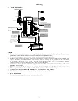
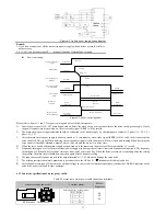
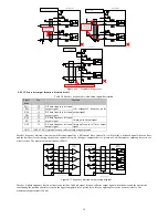
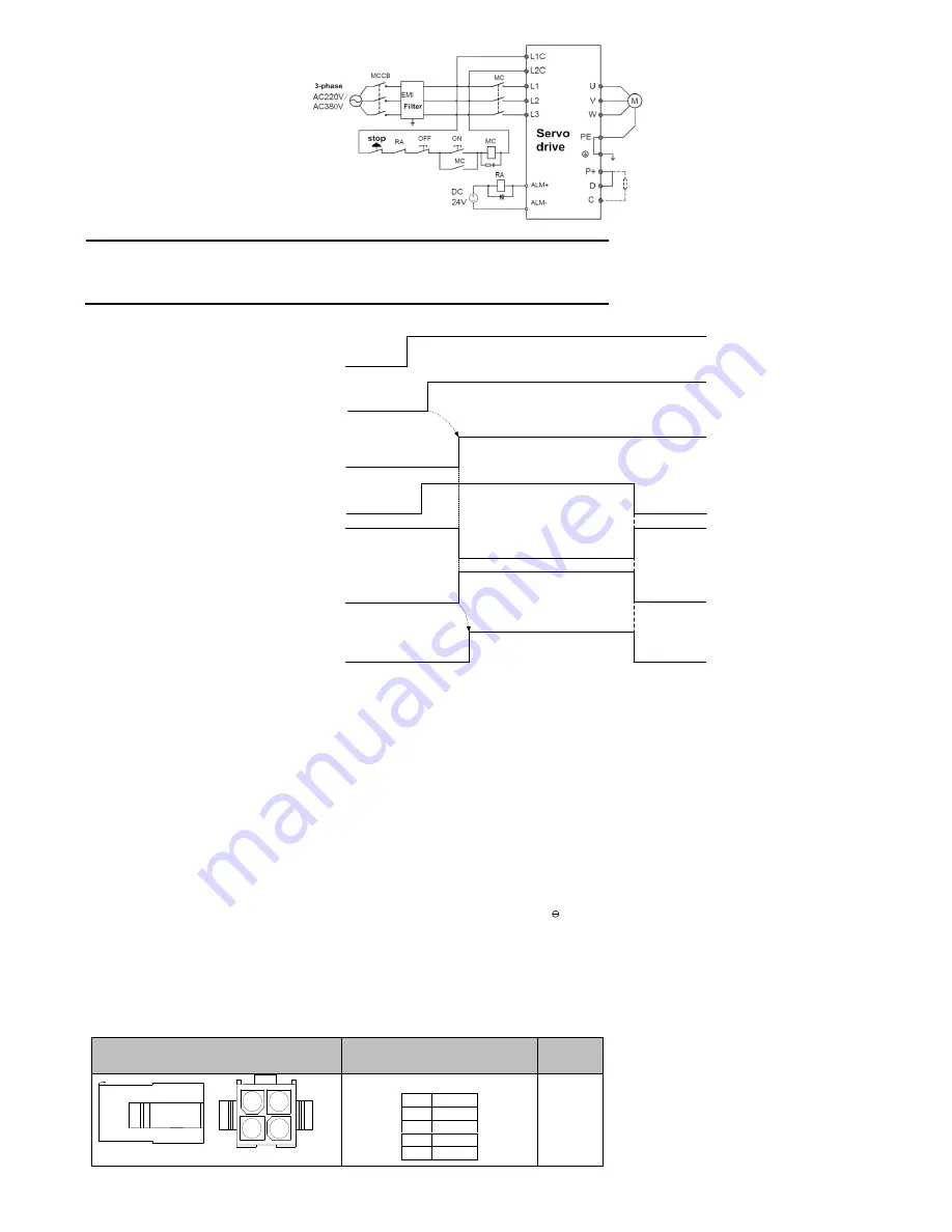
Figure 4-2 3-phase power supply wiring diagram
Remark:
1: If you do not want to cut off the main circuit power supply when a failure occurs, RA relay is
not necessary.
2: L1C, L2C can be connected to P +, - terminals instead of external power supply.
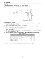
Power on timing
Control circuit power
supply
Mains supply
Servo ready output
(
S-RDY)
Servo enable
(
S-ON )
Servo motor
excitation
Unpowered
Powered
Unpowered
Powered
Not ready
Ready
Enable invalid
Not receive
instruction
Motor
Unpowered
Motor
powered
Not receive
instruction
Receive instruction
Position / speed /
Torque command
Delay1.5S
Delay as P1-54 set
Servo enable signal
(
S-ON signal)
Invalid
Valid
Invalid
Enable invalid
Motor
Unpowered
Enable valid
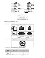
Figure 4-3 power-on timing chart
Please refer to figure 3-1 and 3-2 for power wiring and wire as followed sequence.
1)
Control power circuit L1C, L2C must be powered on before the main circuit or at the same time as the main circuit power supply. If only
the power control circuit is powered on, the servo ready signal (S-RDY) will be invalid.
2)
The main circuit power input terminals should be connected to the mains supply by electromagnetic contactor (3-phase: L1, L2, L3, 1
phase: L1, L2).
3)
After the main circuit power supply is powered on and a 1.5-second delay, servo ready signal (SRDY) will be valid, then it can accept the
servo enable (S-ON) signal. When detecting the servo enable signal is valid, the motor will be activated, and running. When detecting the
servo enable is invalid or alarmed, output of drive will be off, and the motor is in a free state.
4)
When the servo enable and the mains supply are powered on at the same time, the motor will be activated after 1.5 second.
5)
Frequently turning on or off of the main circuit power supply may damage the soft start circuit and dynamic braking circuit. The frequency
of tuning on or off should be less than 5 times one hour, and 30 times one day. When the drive or motor is overheating, after the solving
the problem, the main circuit should be powered on again after 30 minutes cooling.
6)
The input power cable cannot connect to the output terminals U, V, W, which can damage the servo drive.
7)
The braking resistor is absolutely prohibited to be connected to the DC bus P +,
terminals, which may lead a fire.
8)
After the power is turned off, there may be residual voltage in the servo drive internal capacitance, confirm the CHARGE indicator on the
servo drive panel is off before other operation.
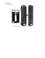
4.2.3 Connector specification of motor power cables
Table 4-2 motor servo motor power cable connection terminals
Connector shape and model
Terminal pinout
Motor
flange size
1
2
3
4
Shell model
:
C4140HM-2X2P
4PIN AMP Plug
(
without brake
)
Pin
Define
1
U
2
V
3
W
4
PE
60
80
86


