30
2KΩ
100Ω
100Ω
1
33
34
100Ω
100Ω
31
32
16
PULSE+
SIGN
-
COM
+24V
PULHIP
PULHIS
25
SIGN+
PULSE
-
Servo drive
PE
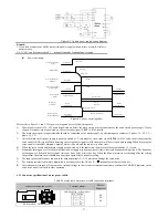
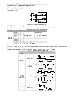
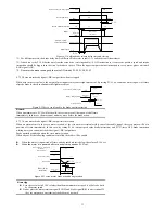
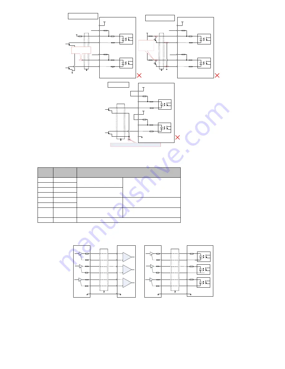
Error 3: SIGN port missed, So that
the two ports can not receive pulse
VCC
R1
SIGN signal
missing
2KΩ
100Ω
100Ω
1
33
34
100Ω
100Ω
31
32
16
PULSE+
SIGN
-
+24V
PULHIP
PULHIS
25
SIGN+
PULSE
-
Servo drive
PE
Error 4: wrong port, so that the port
may be burned
VCC
The collector
signal dose not
access to the
specified port
COM
2KΩ
2KΩ
2KΩ
100Ω
100Ω
1
33
34
100Ω
100Ω
31
32
36
16
PULSE
-
SIGN
-
COM
+24V
+24V
PULHIP
PULHIS
+24V电源
+24V电源
25
PULSE+
SIGN+
36 pin is not connected. And unable to form a closed loop
Servo drive
PE
25
2KΩ
Error 5: Signal loop is not
formed
Figure 4-16 5 typical wiring errors
4.4.9 CN4 encoder output frequency division circuit
Table 3-8 Encoder frequency division output signal description
Signal
name
Pin
Function
PA+
28
A Phase frequency division
output signal
A,B orthogonal frequency pulse
output signal
PA-
13
PB+
12
B Phase frequency division
output signal
PB-
27
PZ+
11
Z Phase frequency division
output signal
Origin pulse output signal
PZ-
26
OCZ
35
Z Phase frequency division
output signal
Origin pulse open collector output
signal
GND
14/42/43/44 Origin pulse open collector output signal ground
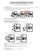
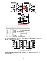
Encoder frequency division circuit output differential signals by a differential drive. Generally, it will provide a feedback signal when the drive
and the host device constituting the position control system. In the upper computer device, please use a differential or optocoupler receive as
circuit receive. The maximum output current is 20mA.
28
PA
-
GND
PA+
Differential receive
PB+
PB
-
PZ+
PZ-
Upper
computer
13
12
27
11
26
14
GND
28
PA
-
GND
PA+
Optocoupler receive
PB+
PB
-
PZ+
PZ-
Upper
computer
13
12
27
11
26
14
GND
PE
PE
Servo drive
Servo drive
Figure 4-17 frequency division output wiring diagram
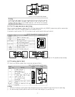
Encoder Z-phase frequency division circuit can provide a feedback signal by open collector output signal when the drive and the host device
constituting the position control system. In the upper computer device, please use a relay or optocoupler receive as circuit receive. The
maximum output current is 40mA.


