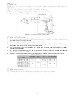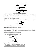
36
100Ω
PULSE+
PULSE-
33
34
SIGN+
SIGN-
31
32
16
PULHIS
PULS
[CW A phase]
SIGN
[CCW Bphase]
Torque
instruction
8
23
37
38
9
24
39
10
DO1
DO1-
DO2
DO2-
DO3
DO3-
DO4
DO4-
Status
output
Encoder
Dividing
pulse output
- Difference
PE
PA+
PA-
PB+
PB-
PZ+
PZ-
28
13
12
27
26
GND
29
11
35
42
Upper
computer
GND
Encoder Z-phase
open-collector output
GND
OCZ
+5V
+5V
GND
6
43
GND
AO1
Analog 1 output
Analog 2 output
15
29
30
29
GND
GND
AI2
AI1
1
EA100
Servo drive
Servo ready
Brake output
Location arrival
Fault output
Torque
limit
PE
Torque limit 0 ~ 10V
Input impedance about:
9kΩ
Torque limit -10 ~ 0V
Input impedance about:
9kΩ
In 5V power
supply, the maximum
allowable current 200mA
PULHIP
+24V
+24V电源
25
COM+ 21
DI1
5
DI2
20
4
DI3
19
3
18
2
DI4
DI5
DI6
DI7
17
DI8
ALM-RST
INHIBIT
P-OT
N-OT
GNUMO
GNUM1
S-ON
P-CLR
COM
State
input
7
Servo enable
Alarm reset clear
Pulse Deviation counter clear
Pulse inhibit
Forward Drive inhibit
Reverse drive inhibit
Electronic gear ratio numerator
selection 0
Electronic gear ratio numerator
selection 1
S-RDY
BK
COIN
ALM
2KΩ
2KΩ
A
GND
AO1
A
100Ω
100Ω
100Ω
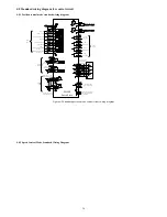
Figure 4-26 standard torque mode control circuit wiring diagram
4.9 Control circuit wiring precaution
Encoder cable routing must be separated from the power cable routing by at least 30cm or more.
If the control circuits need to extend, make sure the shield is reliable connected.
In the servo drive, + 24V COM and + 5V reference to GND. Do not exceed the maximum allowable load current, otherwise the drive may
be broken.
Try to use the shortest command input and encoder cable.
Please use the cable more than 1.5mm
2
for grounding cable.
Must be a single-point ground.
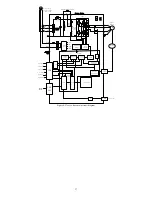
4.10 Servo drive main circuit block diagram


