background image

61

GR

σε


καλή


κατάσταση

Πριν


χρησιμοποιήσετε


την


αντλία


ανάκτησης

βε

-

βαιωθείτε


ότι


είναι


σε


ικανοποιητική


κατάσταση


λειτουργίας

έχει


καλά


συντηρηθεί


και


ότι


όλα


τα


συναφή


ηλεκτρικά


εξαρτήματα


είναι


σφρα

-

γισμένα


για


να


αποφευχθεί


η


ανάφλεξη


σε


περίπτωση


απελευθέρωσης


ψυκτικού


μέσου

Συμβουλευτείτε


τον


κατασκευαστή


σε


περίπτωση


αμ

-

φιβολίας


Το


ανακτημένο


ψυκτικό


μέσο


επιστρέφεται


στον


προμηθευτή


ψυκτικού


μέσου


στη


σωστή


φιάλη


ανάκτησης


και


το


σχετικό


σημείωμα


μεταφοράς


αποβλήτων


τοποθετείται

Μην


αναμιγνύετε


ψυκτικά


μέσα


σε


μονάδες


ανάκτησης


και


ειδικά


σε


φιάλες

.

Εάν


πρόκειται


να


αφαιρεθούν


συμπιεστές


ή


λάδια


συμπιεστή

βεβαιωθεί

-

τε


ότι


έχουν


εκκενωθεί


σε


αποδεκτό


επίπεδο


για


να


βεβαιωθείτε


ότι


το


εύφλεκτο


ψυκτικό


μέσο


δεν


παραμένει


εντός


του


λιπαντικού

Η


διαδικα

-

σία


εκκένωσης


πραγματοποιείται


πριν


από


την


επιστροφή


του


συμπιεστή


στους


προμηθευτές

Για


την


επιτάχυνση


αυτής


της


διαδικασίας


πρέπει


να


χρησιμοποιείται


μόνο


ηλεκτρική


θέρμανση


στο


σώμα


του


συμπιεστή

Όταν


το


λάδι


αποστραγγίζεται


από


ένα


σύστημα

πρέπει


να


εκτελείται


με


ασφάλεια

.

Summary of Contents for SNG21-09IVi

Page 1: ...ODELS SNG21 09IVi SNG21 09IVo SNG21 12IVi SNG21 12IVo SINGER Thank you for your choice in SINGER Wall Mounted Air Conditioners Before using this product be sure to read this Instruction Manual careful...

Page 2: ...2 4 5 6 10 11 12 13 14 22 23 23 24 26 27 30 32 33 35 36 36 37 43 43 47 48 48 50 50 52 52 52 53 54 55 58 58 61...

Page 3: ...3 GR 1 2 3 4 5 6 7 service...

Page 4: ...4 GR R32 R32 GWP 675 R32 R32 R32...

Page 5: ...5 GR service 4m2 R32 1 band wifi 2400MHz 2483 5MHz 2 wifi 20dBm...

Page 6: ...6 GR q q q q q q q q q blue fins q...

Page 7: ...7 GR q q q q q q q q q...

Page 8: ...8 GR q q q q q q 3 q q q q...

Page 9: ...9 GR q q q q q q q NEC CEC q q q q q...

Page 10: ...10 GR q q q q q q q q q q m2 49 q...

Page 11: ...11 GR DB WB C DB WB C 32 23 43 26 27 24 18 15 C 43 C Temp indicator Power indicator aux...

Page 12: ...12 GR...

Page 13: ...13 GR I Feel TURBO AUTO 8 C X FAN WiFi LIGHT...

Page 14: ...14 GR q q beep q q Light 1 ON OFF 2 MODE AUTO COOL DRY FAN HEAT AUTO AUTO FAN SWING...

Page 15: ...15 GR COOL c d FAN SWING DRY SWING FAN FAN SWING HEAT c d FAN SWING 1 5 16 30 C 3 FAN AUTO AUTO...

Page 16: ...16 GR AUTO DRY X FAN FAN 2 AUTO FAN HEAT 2 FAN 4 SWING 2...

Page 17: ...17 GR 5 TURBO Turbo Turbo 6 c d c d 1 C 2 AUTO TIMER ON TIMER OFF CLOCK c d 7 SLEEP Sleep 8 TEMP...

Page 18: ...18 GR 3 5 9 WIFI WiFi WiFi 5 WiFi WiFi MODE WiFi 1 WiFi 10 Light...

Page 19: ...19 GR 11 CLOCK CLOCK c d 5 c d c d 2 CLOCK 24 5 TIMER ON TIMER OFF 12 TIMER ON TIMER OFF TIMER ON TIMER ON ON c d c d 1 c d TIMER ON TIMER ON TIMER ON TIMER OFF TIMER OFF OFF c d c d...

Page 20: ...20 GR 1 c d TIMER OFF FF TIMER OFF TIMER OFF TIMER ON TIMER OFF TIMER ON TIMER OFF TIMER ON TIMER OFF ON OFF TIMER ON TIMER OFF TEMP CLOCK SE TEMP CLOCK Energy Saving...

Page 21: ...aving TURBO SLEEP ENERGY SAVING Energy Saving Sleep Energy Saving Sleep TEMP CLOCK Sleep Energy Saving 8 C TEMP CLOCK 8 C 8 C TEMP CLOCK 8 C 8 C TURBO SLEEP 8 C 8 C Sleep 8 C 8 C TEMP CLOCK Sleep 8 C...

Page 22: ...22 GR I FEEL c d c d LOCK MODE d MODE d C F 1 ON OFF 2 MODE 3 c d AUTO 4 FAN 5 SWING...

Page 23: ...23 GR 1 2 7 1 5V 3 8 aux AUTO...

Page 24: ...24 GR 1 2 aux...

Page 25: ...25 GR 3 45 C 4 1 2 3 4...

Page 26: ...26 GR service 5 service 1 2 3 service 1 2...

Page 27: ...27 GR 3 8...

Page 28: ...28 GR 3...

Page 29: ...29 GR AUTO AUTO 16 C 30 C...

Page 30: ...30 GR 5 8 U8 H6 H3 E1 C5 F1 F2 F0...

Page 31: ...31 GR 210 5386490...

Page 32: ...32 GR 15cm 250 cm 15cm 300cm 15cm...

Page 33: ...33 GR 50cm 30cm 30cm 50cm 200cm...

Page 34: ...34 GR 1 2 3 4 5 6 7 8 1 2 3 4 5 6 2 5 7 8...

Page 35: ...35 GR 1 2 3 4 5 1 2 3 4 5 6 7 8...

Page 36: ...36 GR 9 R32 1 2 3 4 5 9 12 10 17 21 16...

Page 37: ...37 GR 1 2 3 1 150mm 150mm 55mm 70mm 55mm 70mm...

Page 38: ...38 GR 2 3 55 70 5 10 1 2 55 70 5 10...

Page 39: ...39 GR 1 2 3 4 1 m 1 4 15 20 3 8 30 40 1 2 45 55 5 8 60 65 3 4 70 75...

Page 40: ...40 GR 2 1...

Page 41: ...41 GR 2 3 4 5 M 9K 12K N 1 3 2...

Page 42: ...42 GR 1 2 3 4 1 2 3...

Page 43: ...43 GR 4 5 1 2 3 3...

Page 44: ...44 GR 2300W 5000W 6000W 8000W 10000W 16000W 1 2 1 2 1...

Page 45: ...45 GR 2 3 4 1 m 1 4 15 20 3 8 30 40 1 2 45 55 5 8 60 65 3 4 70 75...

Page 46: ...46 GR L N M M 9K 12K 2 1 10 2 U U...

Page 47: ...47 GR O O O...

Page 48: ...48 GR 1 2 3 0 1 4 1 2 0 1MPA 5 6 2 7 Lo Hi...

Page 49: ...49 GR mm A mm A mm 6 6 35 1 4 1 3 0 7 9 52 3 8 1 6 1 0 12 12 7 1 2 1 8 1 0 15 8 16 5 8 2 4 2 2 90...

Page 50: ...50 GR 1 2 3 1 2 ON OFF MODE AUTO COOL DRY FAN HEAT 16oC 1 5 7 5 8 2 3 3...

Page 51: ...5000 BTU h 1465W 7000 BTU h 2051W 9000 BTU h 2637W 15 12000 BTU h 3516W 20 18000 BTU h 5274W 24000 BTU h 7032W 25 28000 BTU h 8204W 36000 BTU h 10548W 42000 BTU h 12306W 48000 BTU h 14064W 30 4 10 5m...

Page 52: ...52 GR g m g m g m 1 4 3 8 1 2 16 12 16 1 4 3 8 5 8 3 4 40 12 40 1 2 3 4 7 8 80 24 96 5 8 1 1 1 4 136 48 96 3 4 200 200 200 7 8 280 280 280...

Page 53: ...4 5 16 8 19 3 22 24 8 27 8 5 2 6 1 7 7 9 8 9 10 1 6 1 9 2 1 2 4 2 8 3 1 1 1 1 3 1 4 1 6 1 8 2 1 m2 kg 1 9 2 2 1 2 2 2 3 2 4 2 5 31 34 3 37 8 41 5 45 4 49 4 53 6 11 2 12 4 13 6 15 16 3 17 8 19 3 3 4 3...

Page 54: ...54 GR 2...

Page 55: ...55 GR R32...

Page 56: ...56 GR 1 2...

Page 57: ...57 GR 3 30 40 1 4 5 6...

Page 58: ...58 GR 7 8 Ampere...

Page 59: ...59 GR...

Page 60: ...60 GR 80...

Page 61: ...61 GR...

Page 62: ...CE 80 81 TROUBLE CAUSE SOLUTION 82 84 INSTALLATION DIMENSION DIAGRAM 85 88 SAFETY PRECAUTION 88 GROUNDING REQUIREMENT 89 INSTALLATION OF INDOOR UNIT 89 95 INSTALLATION OF OUTDOOR UNIT 95 99 VACUUM PUM...

Page 63: ...ain or use the product with other equipment without abiding by the instruction manual of manufacturer After verification the defect of product is directly caused by corrosive gas Afterverification the...

Page 64: ...ns to accelerate the defrosting process or to clean other than those recommended by the manufacture Should repair be necessary contact your nearest authorized Service Center Any repairs carried out by...

Page 65: ...onditioner Otherwise it may cause electric shock q If the supply cord is damaged it must be replaced by the manufacturer its service agent or similarly qualified persons to avoid a hazard q DO NOT was...

Page 66: ...operates under abnormal conditions it may cause malfunction electric shock or fire hazard q When turning on or turning off the unit by emergency operation switch please press this switch with an insu...

Page 67: ...d by the manufacturer its service agent or similarly qualified persons to avoid a hazard q The temperature of refrigerant circuit will be high please keep the interconnection cable away from the coppe...

Page 68: ...or children and far away from animals or plants If it is unavoidable please add the fence for safety purpose q The indoor unit should be installed close to the wall q Instructions for installation and...

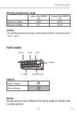
Page 69: ...eating 27 24 18 NOTICE The operating temperature range outdoor temperature for heat pump unit is 15 C 43 C PARTS NAME DISPLAY Temp indicator Power indicator Notice Actual product may be different from...

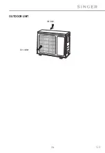
Page 70: ...70 GB OUTDOOR UNIT Air inlet Air outlet...

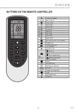
Page 71: ...Fan mode Heat mode Sleep mode 8 heating function not available Health mode X FAN function Clock Set temperature WiFi function optional Set time TIMER ON TIMER OFF Light Up down swing Child lock Scave...

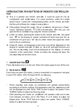
Page 72: ...icon will be displayed on the display of remote controller If timer on timer off and light functions are set the corresponding icons will be displayed on the display of remote controller at the same...

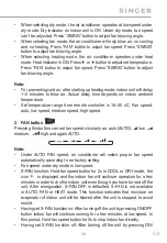
Page 73: ...n speed auto low speed medium speed high speed 3 FAN button Pressing this button can set fan speed circularly as auto AUTO low medium high and again AUTO Note Under AUTO FAN speed air conditioner will...

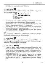
Page 74: ...del When air conditioner receives this signal the air conditioner will blow fan automatically 5 TURBO button Under COOL or HEAT mode press this button to turn to quick COOL or quick HEAT mode icon is...

Page 75: ...rature not available Note Outdoor temperature display is not available At that time indoor unit receives signal while it displays indoor set temperature It is It s defaulted to display set temperature...

Page 76: ...After each pressing of cord button TIMER ON setting will increase or decrease 1min Hold cordbutton 2s later and the time will change quickly until reaching your required time Press TIMER ON to confirm...

Page 77: ...neously again to exit energy saving function Note Under energy saving function fan speed is defaulted at auto speed and it can t be adjusted Under energy saving function set temperature can t be adjus...

Page 78: ...mote controller near user when this function is set Do not put the remote controller near the object of high or low temperature to avoid detecting inaccurate ambient temperature When I FEEL function i...

Page 79: ...Signal may be interfered easily in the room where there is fluorescent lamp or wireless telephone remote controller should be close to indoor unit during operation Replace new batteries of the same m...

Page 80: ...clean the air conditioner Clean surface of indoor unit When the surface of indoor unit is dirty it is recommended to use a soft dry cloth or wet cloth to wipe it Notice Do not remove the panel when c...

Page 81: ...r 1 Check whether air inlets and air outlets are blocked 2 Check whether air switch plug and socket are in good condition 3 Check whether filter is clean 4 Check whether mounting bracket for outdoor u...

Page 82: ...receiving window Select proper angle and point the remote controller at the receiving window on indoor unit Is sensitivity of remote con troller low fuzzy display and no display Check the batteries I...

Page 83: ...indoor air is cooled rapidly After a while indoor temperature and humidity will be de crease and mist will disap pear Set temperature cannot be adjusted Unit is operating under auto mode Temperature...

Page 84: ...he sound of friction caused by expansion and or contraction of panel or other parts due to the change of temperature Error Code When air conditioner status is abnormal temperature indicator on indoor...

Page 85: ...smell There is a leakage from the indoor unit DO NOT repair or refit the air conditioner by yourself If the air conditioner operates under abnormal conditions it may cause malfunction electric shock o...

Page 86: ...wrench Open end wrench Pipe cutter Leakage detector Vacuum pump Pressure meter Universal meter Inner hexagon spanner Measuring tape Space to the ceiling at least 50cm Drainage pipe Space to the wall a...

Page 87: ...appliance shall not be installed in the laundry 8 It is not allowed to be installed on the unstable or motive based structure such as a truck or in the corrosive environment such as chemical factory I...

Page 88: ...ulations use qualified power supply circuit and air switch 3 Make sure the power supply matches with the requirement of air conditioner Unstable power supply or incorrect wiring may result in electric...

Page 89: ...ty regulations 4 The appliance must be positioned so that the plug is accessible 5 An all pole disconnection switch having a contact separation of at least 3 mm in all poles should be connected in fix...

Page 90: ...el is for illustrative purposes only please refer to the actual installation The wall panel is for illustrative purposes only please refer to the actual installation Please refer to the actual circums...

Page 91: ...case Step five Connect the pipe of indoor unit 1 Aim the pipe joint at the corresponding Bellmouth 2 Pretightening the union nut with hand 3 Adjust the torque force by referring to the following sheet...

Page 92: ...re of indoor unit Note All wires of indoor unit and outdoor unit should be connected by a professional If the length of power connection wire is insufficient please contact the supplier for a new one...

Page 93: ...de 3 Remove the wire clip connect the power connection wire to the wiring terminal according to the color tighten the screw and then fix the power connection wire with wire clip Note The wiring board...

Page 94: ...and gas pipe should be bound separately at the end Note The power cord and control wire cannot be crossed or winding The drain hose should be bound at the bottom Step nine Hang the indoor unit 1 Put...

Page 95: ...ith expansion screws Note Take sufficient protective measures when installing the outdoor unit Make sure the support can withstand at least four times of the unit weight The outdoor unit should be ins...

Page 96: ...Place the outdoor unit on the support 2 Fix the foot holes of outdoor unit with bolts Step four Connect indoor and outdoor pipes 1 Remove the screw on the right handle of outdoor unit and then remove...

Page 97: ...ire clip connect the power connection wire and signal control wire only for cooling and heating unit to the wiring terminal according to the color fix them with screws pipe joint union nut Hex nut dia...

Page 98: ...bly and hidden possibly Min semidiameter of bending the pipe is 10 cm 2 If the outdoor unit is higher than the wall hole you must set a U shaped curve in the pipe before pipe goes into the room in ord...

Page 99: ...p and maintain this status for 1 2 minutes to check if the pressure of of piezometer remains in 0 1MPa If the pressure decreases there may be leakage 5 Remove the piezometer open the valve core of liq...

Page 100: ...d prevent the burrs from getting into the pipe C Put on suitable insulating pipe D Put on the unit nut Remove the union nut on the indoor connection pipe and outdoor valve install the union nut on the...

Page 101: ...Test operation 1 Preparation of test operation Specify the important notes for air conditioner to the client 2 Method of test operation Put through the power press ON OFF button on the remote control...

Page 102: ...refrigerant charging amount on the basis of liquid pipe Additional refrigerant charging amount prolonged length of liquid pipe x additional refrigerant charging amount per meter Basing on the length o...

Page 103: ...r using the flammable refrigerant It can only be repaired by the method suggested by the equipment s manufacturer INSTALLATION NOTES The air conditioner is not allowed to use in a room that has runnin...

Page 104: ...peration process Checkwhetherthereisfiresourceorpotentialfiresourceinthemaintenance area The naked flame is prohibited in the maintenance area and the no smoking warning board should be hanged Check w...

Page 105: ...ety instructions when installing or moving the unit To ensure the safety of you as well as the device please follow the safety instructions below CHECK AFTER INSTALLATION Check according to the follow...

Page 106: ...r foreign substance in the refrigerant circuit will cause system pressure rise or compressor rupture resulting in injury 2 When installing or moving the unit do not charge the refrigerant which is not...

Page 107: ...or fire 8 Use the specified types of wires for electrical connections between the indoor and outdoor units Firmly clamp the wires so that their terminals receive not external stresses Electric wires w...

Page 108: ...shall be taken in case analysis is required prior to re use of reclaimed refrigerant It is essential that electrical power is available before the task is commenced a Become familiar with the equipme...

Page 109: ...good working order Empty recovery cylinders are evacuated and if possible cooled before recovery occurs The recovery equipment shall be in good working order with a set of instructions concerning the...

Page 110: ...onsibly to promote the sustainable reuse of material resources By ensuring proper product disposal you help prevent potential negative environmental and health impacts Recycling materials will help sa...

Page 111: ...with the general requirements pursuant to the following European Directives LVD 2014 35 EU EMC 2014 30 EU RoHS EU 2015 863 ERP 2011 65 EU RED 2014 53 EU WiFi Wireless maximum transmit power 18dBm Wir...

Page 112: ...ttp www toyotomi gr SERVICE 6 30 210 5386490 Fax 30 210 5313349 This product is made in China 202104v1 It is prohibited to reprint or reproduction of all or part of this manual in any manner without w...

Reviews: