Agriculture Drone User manual
Agriculture Drone User manual
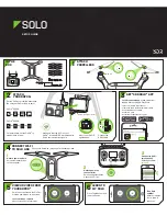
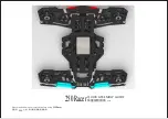
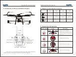
(1).
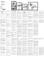
Propellers:
install the propeller correctly according to the marks CCW/CW, put on
the gasket and then tighten with a screw.
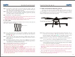
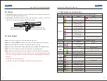
(2). Water pipe connection:
tighten the spray rod, clamping to the drone, connect the
pipes and then connect the pipes to the pump. as follows:
15. Others
press the blue piece when
connect/disconnect the pipe
press the blue piece when
connect/disconnect the pipe
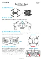
Step1:
turn on the remote control and then power on the drone.
Step2:
after LED flash(
)(10),make a compass calibration (please refer to page 6).
Step3:
after the calibration is complete, install the propellers correctly.
Step4:
wait for GPS signal search, LED will flash singly turn from RED to GREEN if succeed.
Step5:
check if the LED flash correctly according to the correct flight mode.
Step6:
step away from the drone for at least 5 meters, unlock the drone and start flying.
16. First Flight
• Please disconnect the dose detection cable or clear the pesticide breaking point
before
the
compass calibration, in case it may record a wrong breaking point because of
unloading.
• Please operate the joysticks slowly.
• Please keep SA, SB, SC in STANDBY mode before unlocking the drone.
(2)
1)
(2)
(2)
}(10
(
∞
)
}(∞
}(∞
( ∞ )
( ∞ )
(10)
( 5 )
( 4 )
(10)
(10)
( 8 )
(10)
(
(
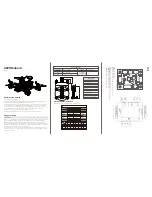
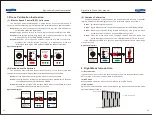
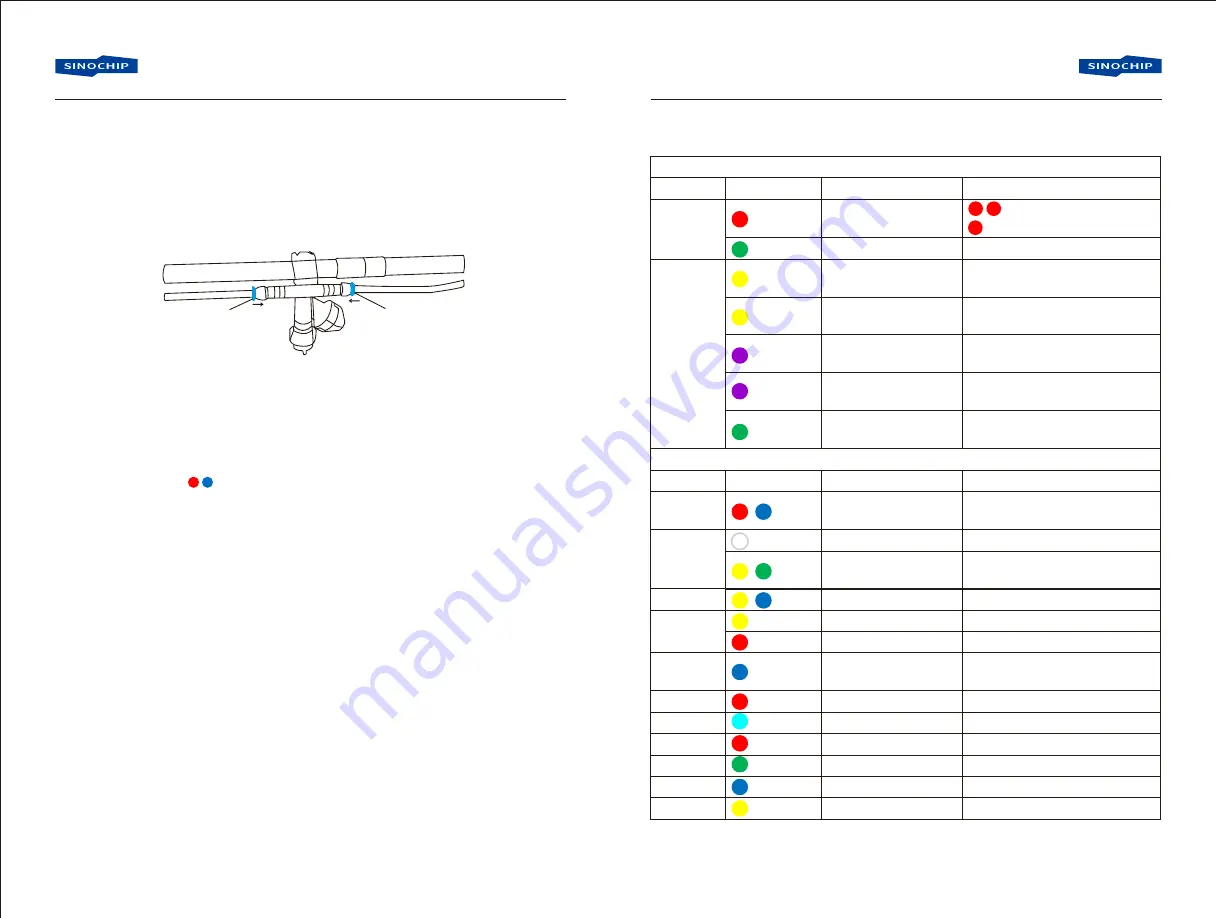
Normal flight indications: first flash GPS status lights, and then flash flight mode lights
Content
GPS status
flight mode
Special status indications: these flashes take precedence over the normal flight indications.
Content
Initialization
status
Sensor
status
RC status
Voltage
status
Return
position
record
location status
breaking point tip
A point record
B point record
A-B route mode
clear AB point
Flash
Flash
(
Hardware initialization,
gyro bias has been
corrected
IMU or barometer data
is abnormal
compass data is abnormal
remote control lose the signal
low voltage alarm level 1
low voltage alarm level 2
record the return position
arrive the specified location
breaking point exist
A point recorded
B point recorded
A-B route available
AB point cleared
Meaning
GPS function unavailable
GPS function available
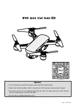
Auto flight mode
Meaning
Remark
(2)GPS signal below level-7
(1)GPS signal above level-7but not good
it flashes in any auto flight mode
such as auto return and auto spraying.
Remark
Check if magnetic interference
and recalibrate the compass
Reconnect the power to see if it
keep in stillness
It records once during the first GPS
positioning as well as ever y time the
motor is started
17. LED Indicator Introduction
11
12
}
}
}
(
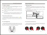
Gesture mode,no
pan & tilt command
Gesture mode with
pan & tilt command
GPS mode, no
pan & tilt command
GPS mode with
pan & tilt command