background image

20 


Quality Check Sheet  - Manual Head Gate S202800 - Serial 
#                                     


Assemble

r(s) Initials 

Quality 

Initials 

1  Verify the short door link assembly S202726 is 20.419": See print on MO. 


2  Verify the long door link assembly S202727 is 45.108". See print on MO. 


3  Ensure nut (699010) and Pivor Spacer Plate (202789) is fully engaged against 

shoulder of pivot rod. 


4  Ensure all center lock nuts are fully engaged and seated on shoulder of threaded 

rods and shoulder screw for pivot assembly. 


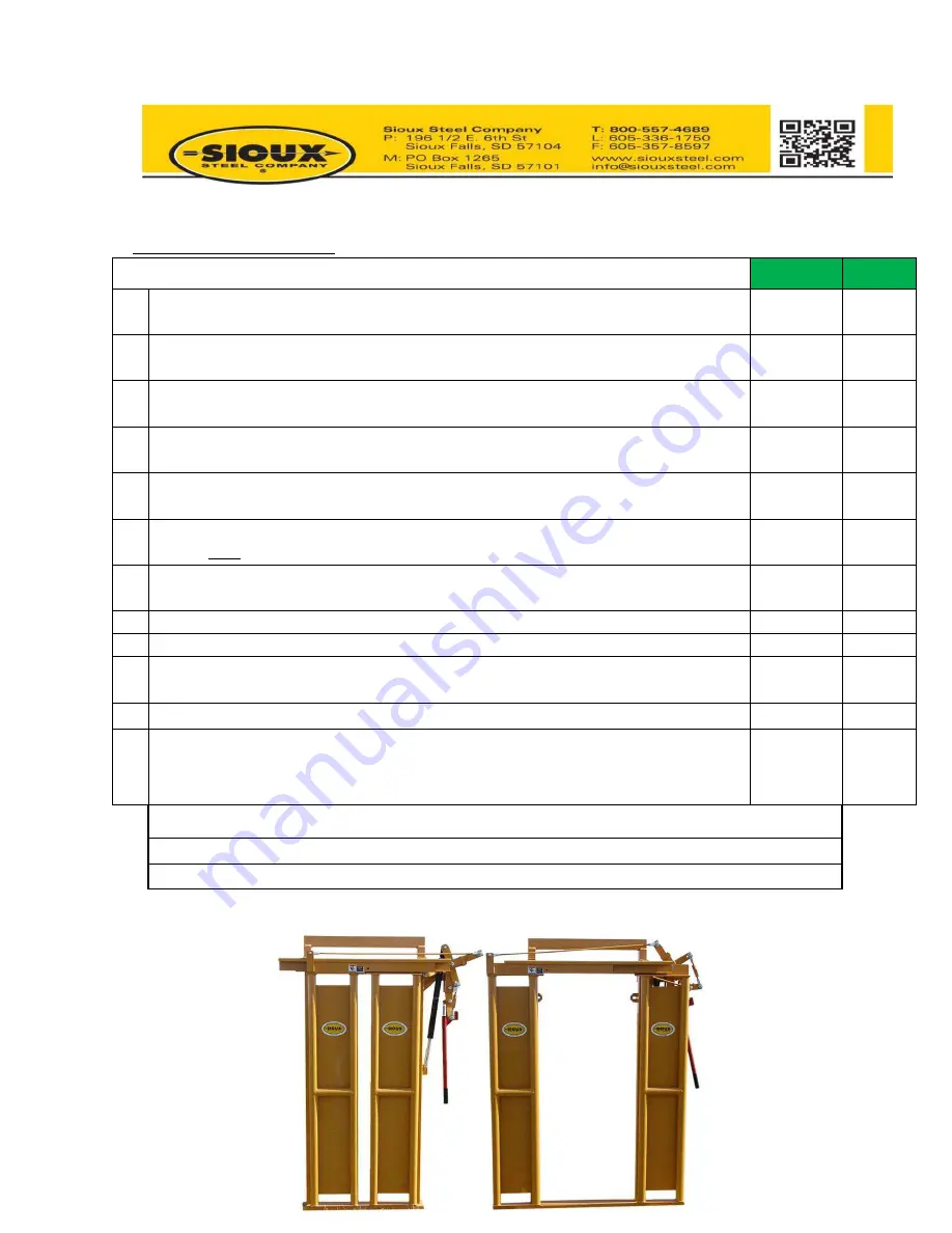
5  Open the head gate and verify a minimum 26" opening on top, 25.25" opening in 

the middle, and 24.5" opening on the bottom. (See Figure 1) 


6  Cycle the head gate 10 times, ensuring to stop for 5 seconds between opening and 

closing 

AND 

each cycle.


7  Close head gate and manually pull open. Then measure gap at the top. The gap 

can't be greater than .50". (See Figures 2 & 3) 


8  Verify grease zerks are greased. (4 total zerks) 


9  Verfiy decals and serial number are placed correctly (See Figure 4) 


10  If head gate is being shipped laying down, verify plug has been placed in vent port 

and breather placed in bag attached to cylinder. 


11  Make sure that the cap nut & jam are tight on cylinder top rod. 


12  Fasten the owners manual and quality check sheet to the head gate with 2 zip ties. 

Also fasten the handle assembly to the frame of the head gate with yellow wire tie. 


Date: 


Assembler Name:                                                                                  Signature: 


Quality Name:                                                                                         Signature: 


Summary of Contents for S202800

Page 1: ...VIDED BREATHER VENT INTO THE TOP CHAMBER OF THE CYLINDER FAILURE TO DO SO CAN RESULT IN INCONSITENT PERFORMANCE IF BREATHER IS ALREADY INSTALLED DISREGARD AND CONTINUE READING OPERATORS MANUAL FOR PRO...

Page 2: ...2...

Page 3: ...2 19 ECN 19 044 Manual Head Gate S202800 LH S208753 RH Left Handed Version Depicted WARNING Keep hands and fingers away from all hinged and moving parts during operation Sioux Steel Company P O Box 12...

Page 4: ...FORMATION PG 6 PARTS LIST BREAKDOWN LH PG 7 9 PARTS LIST BREAKDOWN RH PG 10 12 ASSEMBLY CYLINDER PG 13 HEAD GATE SET UP PG 14 MAINTENANCE PG 15 TROUBLESHOOTING PG 16 HEAD GATE OPERATION PG 17 WARRANTY...

Page 5: ...perators It is important that all operators be familiar with and follows safety precautions Improper use of equipment can cause serious injury or death 1 Read the operator s manual before operating eq...

Page 6: ...oved from head gate Grease the 4 grease zerks found on the linkage rod ends Oil all other hinged and moving parts Before operation of head gate cycle the head gate at least 10 times ensuring to stop f...

Page 7: ...3 14 S208767 Spacer 1 15 S202726 Short Link Ass y 1 16 S202727 Long Link Ass y 1 17 S208499PG Frame LH 1 18 S201299 Cylinder 1 19 S202789P Pivot Spacer 1 20 S202739 Shoulder Bolt 1 21 K699010 Flange...

Page 8: ...8 See next page for linkage breakdown and details Front View showing short linkage connection...

Page 9: ...9 Rear View of Doors showing short linkage connection...

Page 10: ...e 3 14 S208767 Spacer 1 15 S202726 Short Link Ass y 1 16 S202727 Long Link Ass y 1 17 S208746PG Frame RH 1 18 S201299 Cylinder 1 19 S202789P Pivot Spacer 1 20 S202739 Shoulder Bolt 1 21 K699010 Flange...

Page 11: ...11 See next page for linkage breakdown and details Front View showing short Linkage connection...

Page 12: ...12 Rear View of Doors showing short linkage connection...

Page 13: ...pler 1 7 K194518 Cyl Spring Stop 1 8 K194519 1 3 16 Snap Ring 1 9 K696085 Bearing Ball 1 10 K696086 Conical Spring 1 11 K195857 220 O Ring 3 12 K194527 Cyl Rod 1 13 K194535 Spring Compression 1 14 K19...

Page 14: ...provided breather plug into the top chamber of the cylinder If breather is already installed disregard and proceed to next step Before operation of head gate cycle the head gate at least 10 times ens...

Page 15: ...cel 31 10W Shell AW36 or AW46 Oil measure and set aside 11 ozs of oil 2 Remove cylinder from head gate 3 Remove cylinder actuator and drain oil from the top reservoir 4 Carefully remove the cylinder r...

Page 16: ...a Top plunger may be stuck Lubricate top plunger rod where rod enters top reservoir with an aerosol type lubricant b Verify cap and jam nut on top plunger are tight and set at proper setting to preve...

Page 17: ...ort it may be necessary to give a sharp pull on the handle Operation Open Head Gate Close Head Gate Optional Handle Storage Position Safety Chain Pull Handle Down to Close Head Doors Push Handle Up To...

Page 18: ...18...

Page 19: ...hinder the functionality of the Products E LIFETIME GUARANTEED GATES The Limited Warranty for New Sioux Steel Company Products shall apply to the Lifetime Guaranteed Gates Gates for the life of the or...

Page 20: ...tom See Figure 1 6 Cycle the head gate 10 times ensuring to stop for 5 seconds between opening and closing AND each cycle 7 Close head gate and manually pull open Then measure gap at the top The gap c...

Page 21: ...21...

Reviews: