background image

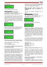
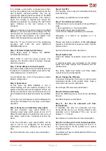
Pressing 

Down

 arrow inactivates the automatic exit

function.

Pressing  

Up

  arrow increases the time with 1 hour

for each keypress up to a maximum of 72 hours.

Press “

C”

  to exit the command and keep the old

setting.

Press  

Enter

  to save the new setting and exit the

command.

Set SIOX Repeats


(Service Mode)

The functions in this menu are only of interest if the
system experiences communication problems.

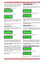
The   number   of   communication   retries   (repeats)
before  a  communication  is deemed  unsuccessful
can be set within the interval 3-30. Normally the
number is 3, which is the factory default. To assist
in troubleshooting  the number of  repeats can be
increased by pressing  

Up

  arrow or decreased by

pressing 

Down

 arrow.

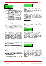
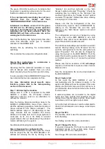
In   the   example   above   number   of   repeats   have
been   increased   to   10.   For   the   lower   line   “H:5”
(“H”=Highest)   means   that   the   module   on
Groupaddress   0   and   Module   address   8   has
needed at most 5 retries. It is the first module with
most retries that is shown. If the module did not
answer at all then “H:10” would be shown because
all   retries   had   been   expended.   To   reset   the
“Highest”-indication   and   restart   a   new
measurement, press 

Right

 arrow. Fault tracing can

then primarily be directed against the bus section
where   the   module   with   most   communication
failures is located.

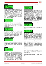
Show system program version


(Service Mode)

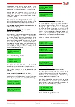
Shows   the   version   of   the   system   program
(firmware).

Press “

C”

 or 

Enter

 to exit the command.

Step-by-Step   instructions   to   commission   a
system using MIDISMOKE_02.cfg

Please note: these instructions are not valid when
the   SMOKE   EDIT   software   is   used.   See   next
section   for   information   about   systems   using
SMOKE EDIT for configuration.

The MIDI SMOKE 2 is normally preloaded with a
configuration   file   (“MIDISMOKE_02.cfg”)  intended
for simpler systems where the key pad is used for
setup. These systems support up to a maximum of
59   damper   modules   (addressed   from   1-59)  

in   a

single   fire   cell

.   Single   or   dual   damper  modules

can be used.

Assuming   that   the   electrical   installation   is   ready
with   all   damper   units   installed,   there   are   a   few
steps necessary to get the system up and running.

For   more   information   about   specific   menu
functions,   please   refer   to   the   corresponding
section in this document.

Step 1: Addressing the modules

Please   note:   if   a   PC   is   connected   to   the   MIDI
SMOKE   2   module,   the   PC-based   software
SioxTools   could   be   used   as   an   alternative   to
address the modules.

Enter the 

Service Mode

 and continue down to the

MODULE ADDRESSING

 menu.

Press  

Enter

  to start the addressing operation and

note that it starts at Group Address=0 and Station
Address=1   which   is   the   address   for   the   first
module. The address range for the modules in the
system will be in the range 1 – 59 depending on
how   many   modules   that   actually   are   installed.
Group Address should always be 0.

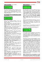
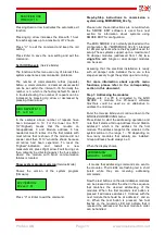
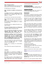
When the display shows...

...it means that addressing commands are sent to
the modules. Their LEDs are flashing red in short
bursts   while   they   are   receiving   addressing
commands.

Now the test buttons on the alarm/damper modules
can be pressed one after the other in the sequence
that   matches   the   desired   addressing   of   the
modules.   When   the   first   module's   test   button   is
pressed it will receive address 1. Continue with the
next module that should be at address 2, and so
on.   When   the   test   button   is   pressed,   five   fast
flashes   on   the   module's  LED  will   indicate   that   it
received the address and the next module in order
can be handled.

Profcon AB

Page 13

www.smokecontrol.net

ADDRESSING             

GROUP:0    ADDR:1     

EX2 VERSION:           
EX2 ver 1.61

SERVICE MODE
TIMEOUT 1 h

SIOX REPEATS:10       
H:5   G:0   A:8

Summary of Contents for MIDI SMOKE 2

Page 1: ...10 Change PIN code 11 Change IP address 11 Change IP gateway address 11 Change subnet mask 11 Change port number for TCP IP 11 Set exercise start delay 12 Show digital input status 12 Show digital out...

Page 2: ...oad the configuration file 15 Step 3 System test 15 Step 4 Set RTC 15 Step 5 Change Pin Code 15 Step 6 Activate watchdog 16 Step 7 Set time for automatic exit from Service Mode 16 Step 8 Switch the sy...

Page 3: ...ommand Digital I O MIDI SMOKE 2 includes four digital inputs to be connected to external open close contacts DI1 terminals 1 2 is the External Fire Input When the contact opens it will indicate Fire A...

Page 4: ...RATION OF WATCHDOG Tc 5 s WATCHDOG 30 s ENT SAVE FUNC TEST SETTINGS T W T F S S I FC1 M 06 00 SETTINGS OF CLOCK DATE 2012 02 10 16 30 FRIDAY SETUP RUN IND OPEN AT FUNC TEST MODULE ADDRESSING ENTER STA...

Page 5: ...STATUS FIRE RESET DI2 OPEN STATUS NIGHT MODE DI3 OPEN Only in Service Mode Not when using SmokeEdit From previous page Only in Service Mode Only in Service Mode Only in Service Mode Only in Service M...

Page 6: ...DO4 CLOSED SET SERVICE MODE TIMEOUT SET SIOX REPEATS EX2 VERSION EX2 v1 61 From previous page Only in Service Mode Only in Service Mode Only in Service Mode Only in Service Mode Only in Service Mode O...

Page 7: ...are version 1 61 it is also required that the communication watchdog be set for the OK LED to be lit To enter Service Mode press F2 and the following text on the display is shown Numbers in the pin co...

Page 8: ...ow adjusts the value Enter sends the value to all modules If the value is set to zero the function is deactivated This is useful during com missioning to stop dampers from closing unex pectedly due to...

Page 9: ...is being performed Module addressing Service Mode This setup menu is used for addressing damper control modules Every module in the system requires a unique address The address consists of a Group ad...

Page 10: ...les Then run the Simple system setup once again When the check passes the text OK CONFIGURATION FOR nn MODULES is displayed The next menu Module configuration will be entered Module configuration Serv...

Page 11: ...change the IP address for the PC or the MIDI SMOKE 2 Change IP gateway address Service Mode Introduced in firmware 1 40 If the unit will be connected to Ethernet the IP gateway address can be changed...

Page 12: ...ange Show digital input status Service Mode For each of the four digital inputs DI1 DI4 there is a menu showing current status to aid in fault tracing Show digital output status Service Mode For each...

Page 13: ...loaded with a configuration file MIDISMOKE_02 cfg intended for simpler systems where the key pad is used for setup These systems support up to a maximum of 59 damper modules addressed from 1 59 in a s...

Page 14: ...a mix of sum alarm night mode functional test and fire alarm If the Run indication relay output DO4 will be used it has to be configured for the desired combination of events otherwise go to the next...

Page 15: ...address set correctly Do this by clicking on the Modules tab and then right click on the Midi Smoke symbol and select Properties Check the watchdog time by clicking on the Modules tab and then right...

Page 16: ...n is approximately 3 5 W Connection of AC power The secondary transformer winding should be connected between terminals 13 G and 14 G0 Connection of DC power Connect the negative supply wire to termin...

Page 17: ...be connected to open close switches See page 1 for a functional description Digital Outputs There are four relay outputs on the MIDI SMOKE 2 Their breaking capacity is 1 A at 30 V AC DC They are norm...

Page 18: ...MidiSmoke2_ProdDescr_12en odt 2018 05 30 YE Profcon AB Page 18 www smokecontrol net...

Reviews: