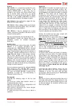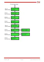
Fire cells
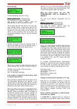
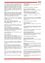
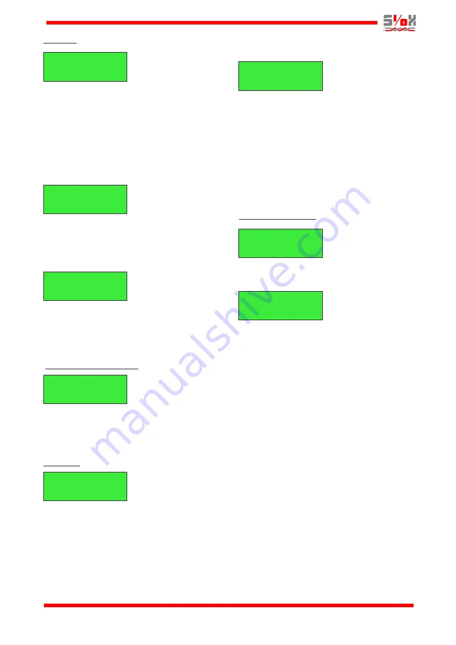
The fire cell above includes two alarm points and
10 dampers. The “A” in “AP” is blinking.
Right/Left
arrow moves the cursor between “A” and “D”.
Pressing
Up
arrow will go to the next fire cell.
Pressing
Down
arrow
will go to the previous fire
cell. Pressing
Enter
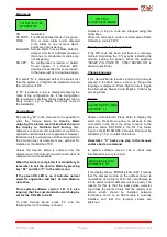
will show a list of the
predefined alarm points or dampers in the current
fire cell as in the examples below. Press
Down
arrow or
Up
arrow to move between the different
alarm points or dampers.
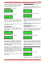
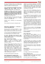
On top is shown the name of the alarm point. The
lower line shows its status. If it is a smoke detector,
a blinking “R” will be shown at the extreme right to
indicate that a reset command can be sent by
pressing
Enter.
On top is shown the name of the damper. The
lower line shows its status and end point indication
(“O” for open, “C” for closed). A blinking “T” will be
shown at the extreme right to indicate that a
function test can be run by pressing
Enter.
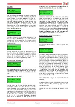
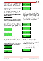
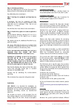
Function test all dampers
Pressing
Enter
will carry out a function test on all
connected damper modules. Normally the dampers
will start with a 5 seconds interval within each fire
cell.
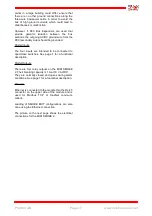
Watchdog
(Service Mode)
This is to set up the maximum acceptable com-
munication interruption time before a module
enters fire alarm mode closing its local damper(s)
and opening its local alarm relay. Tc is a value
describing the current cycle time for the system.
The selected watchdog time must be higher than
Tc. The time can be set to 0 s, 30 s, 40 s, 50 s up
to 90 s in 10 s increments.
If damper modules
have been replaced in the system it is
important that the watchdog configuration is
repeated to initialize the new modules.
Up/Down
arrow adjusts the value.
Enter
sends the
value to all modules. If the value is set to zero the
function is deactivated. This is useful during com-
missioning to stop dampers from closing unex-
pectedly due to disruptions in the execution of the
MIDI SMOKE 2 controller. A cyclically displayed
warning text
“WATCHDOG INACTIVE”
will be
shown in the main menu (not if
Service Mode
is
active) to indicate this condition.
At a convenient
point during the commissioning the watchdog
should be properly set so that dampers will
close if the communication breaks down.
Functional test setup
(Service Mode)
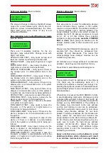
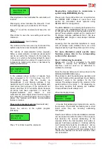
To configure the functional test setup, press the
Enter
key.
The
lower line
shows which days to run a test of
the dampers in the current fire cell and the time of
day. Use the
Left/Right
arrows to change the day
position and also to enter the hours/minutes field.
Use the
Up/Down
arrows to pull the day letters to
the upper or lower line and to increase/decrease
the time. If no weekdays are selected for damper
test the modules will be configured to do function
tests on their own at 48 hours interval (time
counting starts when they are powered up). If the
“I” alternative is selected and no weekdays are
selected it means that the 48 hours interval in the
modules are inhibited. This choice is typically used
if the exercise should only be controlled by digital
inputs or thru Modbus TCP.
Press
Enter
when ready or “
C”
to exit without modi-
fications.
If there are more fire cells to configure the next one
will be shown in the order they appear in the
configuration file.
Default time for functional test is monday 06.00
hrs.
Profcon AB
Page 8
www.smokecontrol.net
FIRE CELL 1
2 AP 10 DAMPERS
DAMPER ST2_1
OK O T
ALARM POINT 1
OK R
FUNC. TEST ALL
DAMPERS? <ENTER>
WATCHDOG SETUP
Tc = 3s
WATCHDOG
30 s (ENT=SAVE)
M T T F S S I FC1
O 06:00
FUNC.TEST
SETTINGS


