77
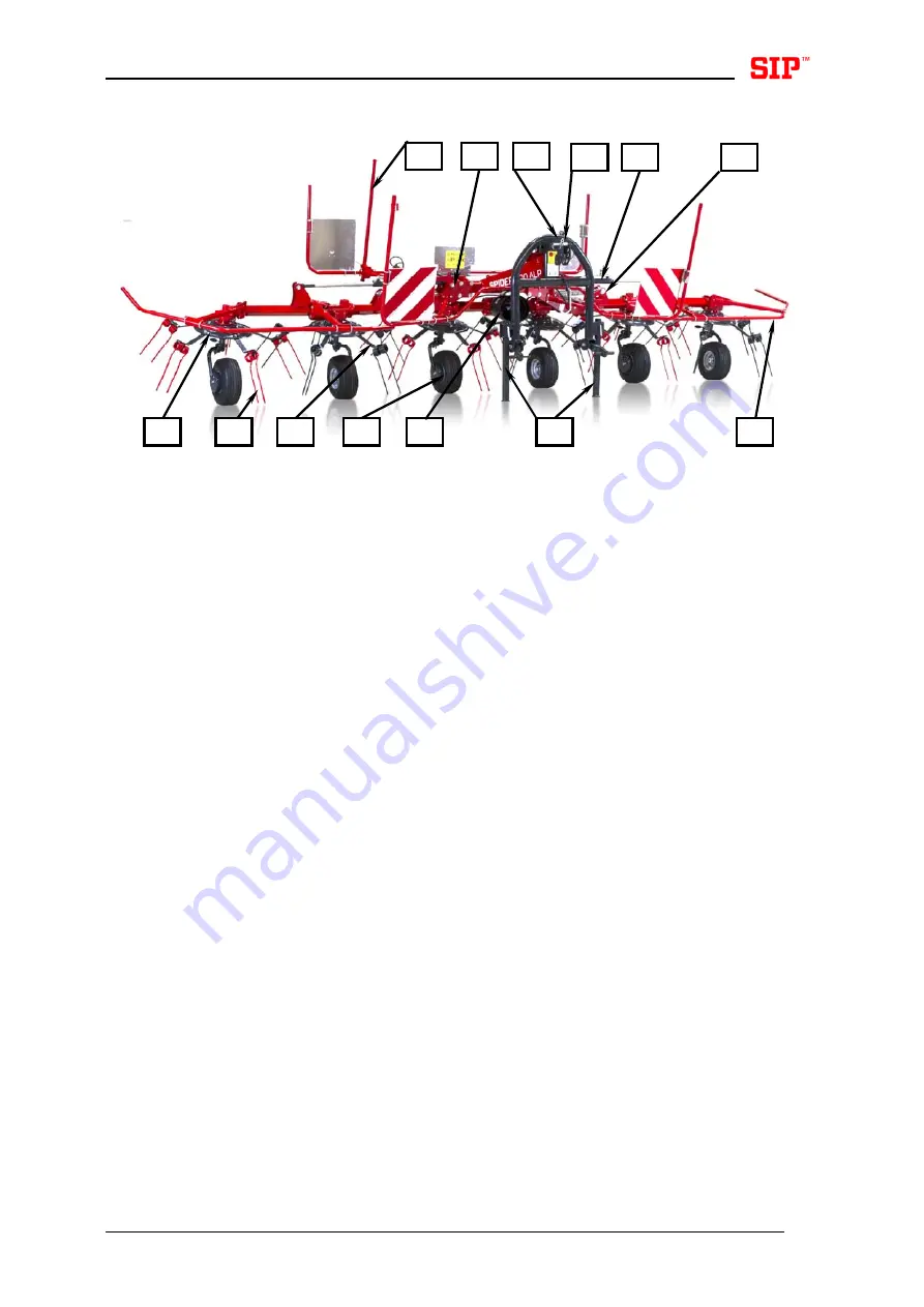
Bild - Figure 1
1. Seitenkreisel
2.
Halter des Federzinkens
3. Federzinken
4. Stützrad
5. Stützbein
6. Schutz
7. Kardanschutz
8. Hydraulikrohr
9. Hydraulikwelle
10. Schnappöse
11. Zugseil
12. Kreiselgelenk
13. Hinteres
Stützbein
1. Side
rotor
2.
Spring tine arm
3. Spring
tine
4. Support
wheel
5. Support
leg
6. Protection
rail
7.
Protection of the PTO shaft
8. Hydraulic
hose
9. Hydraulic
cylinder
10. Rotor hold/for transport position
11. Pull
cord
12. Gear
joint
13. Rear support leg
11
9
6
4
5
7
8
12
3
2
1
10
13
Summary of Contents for SPIDER 600/6 ALP
Page 27: ...23 153928013 7 423580200 8 910093507 9 SPIDER 600 6 ALP 423580220 10...
Page 32: ...28 Slika 2 2 1 4 5 6 5 6 7 8 10 9...
Page 38: ...34 Slika 7 Slika 8 A 1 2 2 3 B...
Page 43: ...39 Slika 11 Slika 12 Slika 13 Slika 14 4 1 2 3...
Page 46: ...42 Slika 17 Slika 18 Slika 19 Slika 20 2 7 5 6 3 4...
Page 56: ...52 Slika 26 1 3 3 2 4 4...
Page 57: ...53 7 6 5...
Page 79: ...75 153928013 7 423580200 8 910093507 9 SPIDER 600 6 ALP 423580220 10...
Page 84: ...80 Bild Figure 2 2 1 4 5 6 5 6 7 8 10 9...
Page 90: ...86 Bild Figure 7 Bild Figure 8 A 1 2 2 3 B...
Page 93: ...89 Bild Figure 9 1 4 3 5 6 2 7 8...
Page 96: ...92 Bild Figure 11 Bild Figure 12 Bild Figure 13 Bild Figure 14 1 2 4 3...
Page 99: ...95 Bild Figure 17 Bild Figure 18 Bild Figure 19 Bild Figure 20 2 7 5 6 3 4...
Page 109: ...105 Bild Figure 26 1 3 3 2 4 4...
Page 110: ...106 7 6 5...
Page 133: ...129 153928013 7 423580200 8 910093507 9 SPIDER 600 6 ALP 423580220 10...
Page 138: ...134 Figura 2 Illustration 2 2 1 4 5 6 5 6 7 8 10 9...
Page 144: ...140 Figura 7 Illustration 7 Figura 8 Illustration 8 A 1 2 2 3 B...
Page 147: ...143 Figura 9 Illustration 9 1 4 3 5 6 2 7 8...
Page 163: ...159 Figura 26 Illustration 26 1 3 3 2 4 4...
Page 164: ...160 7 6 5...


