11
9961A-C Configuration and Connection Guide
C
ONFIGURATION
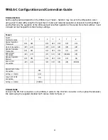
Set the eight-position dipswitch on the 9961A-C per Table 1. Switch 3 may be set to the ON position when
using a Cat 5 cable with a length of longer than 1 meter and marginal operation is observed. Switch settings 7
and 8 affect only the operation of the LEDs and will not affect operation of the cards. Note that switches 1 and
2 should not be changed from their factory settings.
T
ABLE
1
Switch
Position/Function
1
2
3
4
5
6
7
8
Duplex Operation
Transceiver
OFF
OFF
OFF
OFF
OFF
OFF
OFF
HS Port Connection
(UP)
(UP)
(UP)
(UP)
(UP)
(UP)
(UP)
Simplex Operation
Transmitter
OFF
OFF
OFF
OFF
OFF
ON
OFF
End HS Port
Connection
(UP)
(UP)
(UP)
(UP)
(UP)
(DOWN)
(UP)
Simplex Operation
Receiver
OFF
OFF
OFF
OFF
OFF
OFF
ON
End HS Port
Connection
(UP)
(UP)
(UP)
(UP)
(UP)
(UP)
(DOWN)
Normal Cat 5 Cable
Connection
OFF
Setting (<1 Meter)
(UP)
Long Cat 5 Cable
Connection
ON
Setting (>1 Meter)
(DOWN)
C
ONNECTIONS
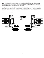
Connect the HS Port connectors on the 9961A-C cards to the HS Port connector on the optical transmission
link cards using the supplied shielded Cat 5 cables. Refer to Figure 2.


