background image

Fig. 25

-

Tighten the plastic head bolts with adequate force to prevent their damage or damage to the nuts in the

unit body.

3. Electrical Installation – Connection to Mains

1.

General Information – Safety

-

Before starting all the installation work, make sure that the wiring box or mains power outlet that you  

want to use to connect the unit is equipped with a protective (green-yellow) wire or contact (pin).

-

If you use a mains plug to connect the unit, it must always remain accessible so that the unit can be
safely disconnected from the mains in the event of danger.

-

Check that the power supply meets the requirements for power supply of the unit (voltage, current,  

frequency, etc.) specified on the unit's serial plate. Section 3.3.3. Displaying the Electrical Parameters.

-

The relevant current circuit must be protected in the electric power distribution system by the
maximum of 16 A.

-

The electrical cable to be connected to the mains must not be broken.

-

Local electrical regulations must always be respected.

-

Electrical connection of the unit to the mains may only be carried out by persons qualified for this  

activity with a valid authorisation and knowledge of relevant standards and directives in the country.

-

Before starting any installation work, it is necessary to switch off the power supply. During the

installation, the switch must be secured against being switched on again by an unauthorised person.  

The switch must have the minimum contact spacing of 3 mm.

-

It is forbidden to interfere in any way with the internal connection of the unit, unauthorised

interventions in the unit may lead to loss of warranty servicing claims

-

This unit belongs to the product group with type Y connection. If the supply cord is damaged, it must
be replaced by the manufacturer, its service centre, or similarly qualified person to avoid dangerous
situations.

-

The unit is classified as protection class 1 category of appliances in terms of protection against electric

shock.

-

The unit supply voltage of 1~230V/50-60Hz may not be modified in any way; otherwise, there is a risk
of damaging the electrical elements of the unit.

3.3.2. Connection to Mains

-

The unit is equipped with a separate strand-type supply cable (stranded wire). The stripping of the cables  
to the individual wires is 50 mm. The individual wires are equipped with crimped terminals.

-

The supply cable length of 1.5 m may be shortened by a qualified person as needed.

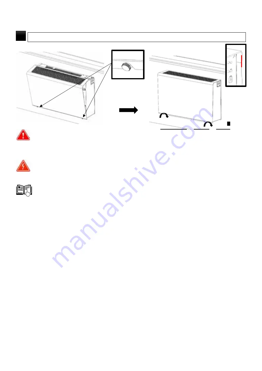
ATTACH THE FRONT COVER, TIGHTEN THE BOLTS BY HAND – ALIGNING THE COVER WITH THE TEMPLATE

3

33

Version 1 – GBR(23/06/2021)

D-502-0152

Summary of Contents for XROOM

Page 1: ...OPERATING AND INSTALLATION MANUAL RECOVERY AND HEATING UNIT XROOM 1 Version 1 GBR 23 06 2021 D 502 0152...

Page 2: ...tting position 4 11 Unit cover position 5 11 Reinforcement position 6 11 Bolt M6x30 position 7 11 Filters position 8 12 2 1 9 Filter caps position 9 12 2 1 10 Preheating position 10 12 2 1 11 Fans pos...

Page 3: ...3 Installation Template Mounting 23 3 2 3 Preparation of Piping Holes in the Existing Wall 24 3 2 4 Preparation of Supply and Drain Piping 25 3 2 4 1 Extension of piping for walls with a thickness gre...

Page 4: ...y in the electric version XR1 xxx ECE1 41 5 4 6 5 4 7 5 4 8 Setting the RequiredTemperature 41 Display of the IndicatedStatuses on the Controller by LEDs 41 Hidden RegulationFunctions 42 5 4 9 Automat...

Page 5: ...serve the right to change this manual without prior notice Children and persons with reduced physical sensory or mental capabilities or lack of experience and knowledge may use the unit only under sup...

Page 6: ...tion but also for space with heating requirements ventilation and heating are independent of each other In case of type configuration with o Electric heating the unit is equipped with advanced regulat...

Page 7: ...eck for any traces of damage on the packaging If the packaging is damaged write a record of the damage and contact your carrier please Check if you have received the product actually ordered by you Af...

Page 8: ...we recommend that you attach the serial plate by default supplied with the package to the operating documentation e g equipment operating book etc which is subsequently kept for a later maintenance r...

Page 9: ...2 Technical Parameters 1 Design of the Xroom unit 1 2 3 4 6 7 5 Fig 1 9 Version 1 GBR 23 06 2021 D 502 0152...

Page 10: ...Fig 2 8 9 13 14 10 11 12 15 16 17 19 19 23 10 Version 1 GBR 23 06 2021 D 502 0152...

Page 11: ...ody of the unit is made of black pressed EPP plastic expanded polypropylene It ensures the accuracy and repeatability of the installation of components The material itself is an advanced technical mat...

Page 12: ...to control the entire unit 2 1 15 Regulator box position15 It ensures interconnection of the individual components and also serves for the customer s connection 2 1 16 FILTER RESET button position16...

Page 13: ...Fig 3 2 2 Main dimensions of the Xroom unit 2 2 1 Xroom 100 XR1 010 EC 2 2 2 Xroom 250 XR1 025 EC Fig 3 13 Version 1 GBR 23 06 2021 D 502 0152 Fig 4...

Page 14: ...minal airflow BOOST m3 h 90 205 Heat output range of heating kW 0 29 1 24 0 5 0 29 1 24 0 5 Noise level dB A 32 1 Weight kg 16 3 18 3 19 3 16 8 18 8 19 8 Water volume in exchanger l 0 51 0 51 Power su...

Page 15: ...nit equipment pre heater electric electric electric after heater water electric water electric Nominal airflow BOOST m3 h 240 335 Heat output range of heating kW 1 34 3 49 1 1 34 3 49 1 Noise level dB...

Page 16: ...cessibility of exterior sound 2 3 3 Technical data of waterheaters XR1 01 ECV1HR heat recovery exchanger XR1 010 ECV1ER enthalpy recovery exchanger XR1 025 ECV1HR heat recovery exchanger 16 Version 1...

Page 17: ...Tab13 Tab 14 XR1 025 ECV1ER enthalpy recovery exchanger 2 3 4 Heat and moisture recoveryefficiency XR1 010 EC 17 Version 1 GBR 23 06 2021 D 502 0152...

Page 18: ...electrical connection point wiring box outlet meets the unit s power supply requirements voltage current etc specified on the unit s serial plate The electrical quantities necessary for the unit s op...

Page 19: ...1 2 3 4 5 6 7 19 Version 1 GBR 23 06 2021 D 502 0152 Fig 5...

Page 20: ...tallation accessories is carried out gradually according to the installation work course as specified in this manual Package Content Description Box 2 A Plastic white tube 125 mm XR1 010 DUCT 1 or 150...

Page 21: ...me amount of air is supplied and discharged and can in no way replace a separate air supply to the furnace For proper operation of the furnace and the unit consult the location with the chimney sweep...

Page 22: ...health and property of the user Take special care when draining the condensate using a condensation sump not a part of the supply into the sewerage piping The unit manufacturer accepts no liability fo...

Page 23: ...ench Save the mounting pins for future use Fig 9 3 2 2 1 Fitting the installation template on the wall when using the construction module If you used a building module XR1 xxx DUCT 1 to build the wall...

Page 24: ...red holes in the installation template to correctly align the piping holes The installation template is also used as a drilling template Do not remove the installation template when drilling the pipin...

Page 25: ...on 3 2 4 1 Measure the total wall thickness with the thickness of the installation template through the drilled hole the thickness of the installation template itself is 2 mm From box 2 installation a...

Page 26: ...ll thickness is over 600 mm If the total wall thickness does not allow for the minimum length of the extension tube to be 100 mm i e wall thickness is between 500 and 600 mm a part of the tube from th...

Page 27: ...nto the lower socket of the unit by turning it back and forth while pushing it down into the groove After fitting the pipe onto the lower socket check its perpendicularity to the rear part of theunit...

Page 28: ...nstalled piping with self tapping bolts 4 x 22 mm against each other as shown in Fig 15 4 at a distance of 20 mm from the edge of the unit see Fig 16 3 2 6 Gluing Insulating Pads For proper sealing of...

Page 29: ...nt cover 3 2 8 Xroom Unit Final Fitting Partly slide the removed unit onto the installation template pins Connect the ground wire connector to the grounding point of the installationtemplate to achiev...

Page 30: ...e inlet and outlet of the heating water the ends of the flexible hoses are marked with red hot water inlet and blue return dots To ensure a flexible hose against turning when tightening use size 27 wr...

Page 31: ...th adequate force BUT MAX 5 Nm so that the fitting sits with its entire rear surface on the installation template Otherwise there is a risk of increased noise and incorrect function of the unit 3 2 9...

Page 32: ...ge through the outlet 3 2 11 Installation of the Front MetalCover Bolt in the M6x20 bolts with the plastic head part of the delivery in a bag about 10 mm to the bottom of the unit o Xroom 100 size 2 p...

Page 33: ...ves in the country Before starting any installation work it is necessary to switch off the power supply During the installation the switch must be secured against being switched on again by an unautho...

Page 34: ...on for this activity and knowledge of the relevant standards and directives in the given country 3 3 2 2 Connecting the Unit to the Electrical Outlet The supply cable can be equipped with a fork with...

Page 35: ...e button Then retract the wire release the lock and slightly pull it out of the terminal to verify that the wire is properly secured If the wire needs to be removed from the terminal the procedure is...

Page 36: ...oom radon concentration is not achieved the control of the unit increases the flow up to the maximum flow value set by the user o the control of the unit starts to decrease the flow rate continuously...

Page 37: ...on off by an external contact it can be switched off on by the controller on the unit An example of the external contact functioning a timer is used as an external contact o EXT1 activates the unit a...

Page 38: ...rrows until the blue status diode left button for the version with electric heating XR1 xxx ECE1 is lit approx 3 sec right button for the version with water heating XR1 xxx ECV1 and without heating co...

Page 39: ...of some functions is only possible from this mode The setting mode is activated by clicking on the button for which the function is to be changed The plus and minus button is intended for activation...

Page 40: ...5 4 2 Description of the functions of the buttons and regulation Tab17 40 Version 1 GBR 23 06 2021 D 502 0152...

Page 41: ...umstances be regarded as binding 6 Setting the Required Temperature 1 In regular mode double click on button 1 or 2 or 3 to enter the settings mode LED 10 flashes fan pictogram 2 As long as the LED 10...

Page 42: ...concentration or complete ventilation of the substance being monitored o When the concentration is reduced to a specified value ventilation is switched off and the unit is switched to the standby mode...

Page 43: ...ot switch off the unit to replace the filter Safe disconnection of electrical parts is provided by the integrated limit switch position 18 After release removal of the front metal cover position 17 th...

Page 44: ...tdown Press and hold the red white FILTER RESET button until the red LED on the controller switches off approx 2 sec o If the control flashes the error message fan error 11 or 12 see Section 8 1 ignor...

Page 45: ...e or the manufacturer Regular maintenance must include o visual inspection of the unit casing Section 7 1 o visual inspection of the supply cable Section 7 1 2 o visual inspection and cleaning of the...

Page 46: ...imit its functions Remove the front metal cover position 1 see Section 6 1 1 and 2 Remove the M6x25 bolts that hold the unit cover position 5 o XR1 010 EC o XR1 025 EC 7 pc 9 pc Slide out the unit cov...

Page 47: ...if the unit is not equipped with preheating to prevent damage to the return damper located in the piping with a common cleaning agent e g soapy water VACUUM THE DRAINAGE PIPING AND WIPE IT FROM OUTSID...

Page 48: ...it so that the bottom edge of the cover and the top edge of the rail of the unit are pressed together Return the M6x25 bolts to secure the cover ANTI FREEZE SENSOR POSITION TURN THE FANS BACK AND INSE...

Page 49: ...ed professionally trained worker and only using original spare parts The manufacturer reserves the right to make changes to the device that do not affect the essential properties of the device 8 1 Err...

Page 50: ...sponsible for electrical waste collection Please return all unwanted or obsolete products and packaging to the relevant recycling sites where they will be disposed of professionally Dispose of the par...

Reviews: