
SiRFatlasV
Hardware Design Guide
January, 2010
SiRF Design Guide
– Proprietary and Confidential
6
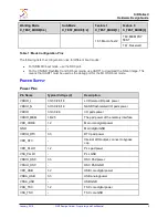
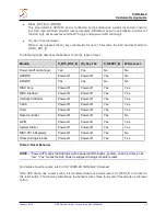
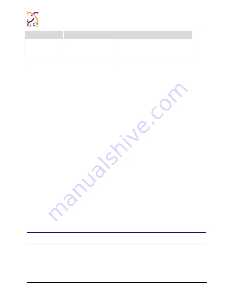
Pin Name
Typical Voltage (V)
Description
VDDA_TSC
3.3
TSC analog power
VSSA_TSC
-
TSC GND
VDDIO_DAC
3.3
MoDAC PAD power
VSSIO_DAC
-
MoDAC PAD GND
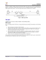
Table 2: Power Pins
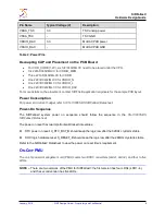
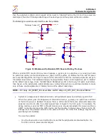
Decoupling CAP and Place ment on
the
PCB Board
For VDD_CORE (1.2V), six 1uF/0402/MLCC need to be placed under the CPU.
Six 220nF/0402/MLCC for VDDIO_MEM
Three 220nF/0402/MLCC for VDDIO
One 220nF/0402/MLCC for VDDIO_N
One 220nF/0402/MLCC for VDDIO_L
One 220nF/0402/MLCC for VDDIO_DAC
For more details on the placement, contact SiRF field application engineers for the sample PCB layout.
Power Consumption
For power and current budget, refer to
: CS-130805-DS SiRFatlasV Datasheet
.
Power-On Sequence
The SiRFatlasV system power on sequence should follow the sequence in the
CS-130805-DS
SiRFatlasV Datasheet
.
The power on reset has two important valid reset time values:
RTC power on reset: X_RTC_RST_B should keep the logic low after the 32KHz crystal is stable
SOC logic hardware reset: X_RESET_B should keep the logic low after the 24MHz crystal is stable
Refer to the SiRFatlasV Datasheet to view the power on reset time
’s requirement.
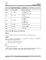
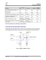
O
N
-C
HIP
PMU
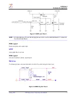
The on-chip power management unit (PMU) covers two DCDC converters (dcdc1, dcdc2), and four to five
LDOs.
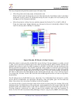
NOTE
–
There are two versions of the PMU for SiRFatlasV: the first version has four LDOs (LDO1~4),
and the second version has five LDOs.