SiRFatlasV
Hardware Design Guide
January, 2010
SiRF Design Guide
– Proprietary and Confidential
12
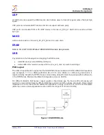
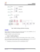
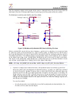
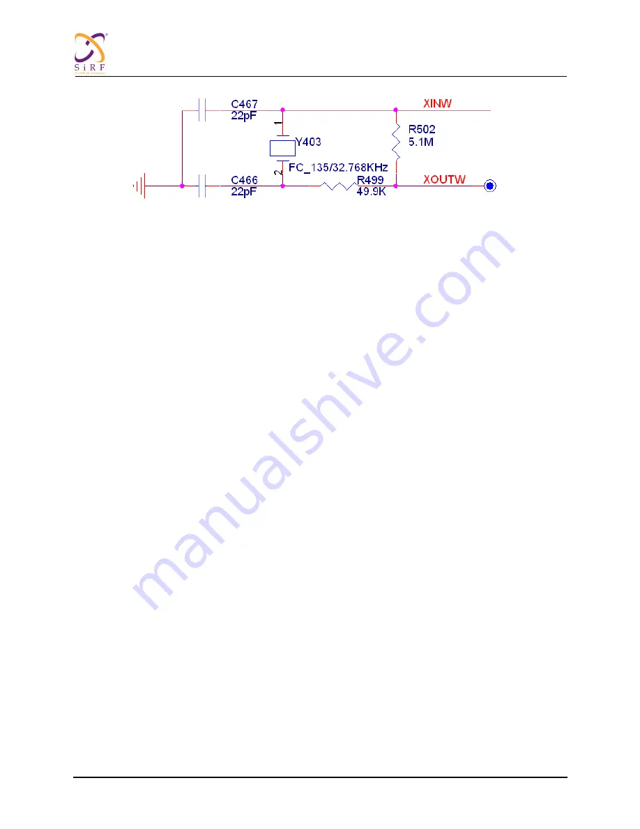
Figure 7: 32.768KHz Crystal Circuit
Crystal part number:
24 MHz, E3SB24.0000F16D23, HOSONIC.
32.768 KHz, 12.5pF, FC-135, EPSON.
PCB Layout
The crystal oscillator is sensitive to stray capacitance and noise from other signals. It can also interfere
with other signals and cause EMI noise. Therefore the load capacitors, crystal and parallel resistors
should be placed close to each other. The ground under the circuit should remain intact.
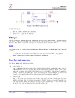
GPIO
If a pin is set to GPIO, then GPIO type and settings should be checked. The following settings should be
avoided:
If a GPIO is set as output, then ensure that the output value does not conflict with peripherals
during running mode for better power consumption management.
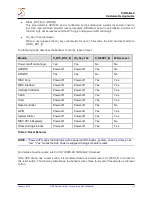
R
ESET
B
UTTON
C
ONNECTION
SiRFatlasV has several reset function pins:
X_RTC_RST_B
This is a reset signal used to reset all RTC domain logic and power on/off control logic. After the
VDDIO_RTC first powers on,
X_RTC_RST_B
should be active to guarantee that the RTC logic is
reset and the power on/off control logic enters the RTC_COLDBOOT state. When the system is
running, any time
X_RTC_RST_B
is active, the RTC logic is reset, causing
X_system_en
and
X_dram_en
to output low, and all SoC power except the RTC power will shutdown.
X_RESET_B
This is a hardware logic reset that resets all SoC logic except the RTC domain logic and power
on/off control logic. After the IO power is supplied,
X_RESET_B
should be active to guarantee the
SoC logic is reset. While the system is running, any time
X_RESET_B
is active, all SoC logic
except the RTC logic and power on/off control logic will be reset