1
2
3 4 5 6 7 8 9
Reader Equipment Installation
4
IN
finity
610
User’s Guide
2
Reader Equipment Installation
2.1.
Mechanical Installation
2.1.1.
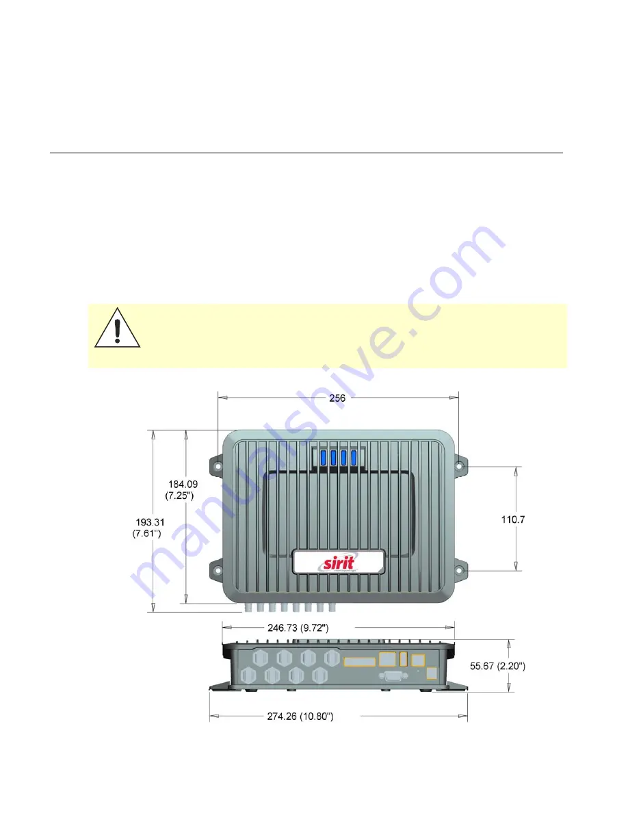
Mounting the Reader
The IN
finity
610 is equipped with two mounting flanges and slotted
keyholes that accept three #8 (M4) mounting screws. Pre-drill any mounting
surface according to the following dimensions. Any mounting surface must
be able to support up to 5 pounds (2.3 kg).
Caution:
The INfinity 610 reader has been designed and tested to meet all regulatory
requirements in the jurisdiction where offered. Any attempt to open the reader
housing or modify the reader in any way will void the reader warranty and may
violate regulatory requirements. Contact Sirit Customer Support for additional
information
Figure 3
IN
finity
610 Mechanical Dimensions (dimensions in mm)
Summary of Contents for INfinty 610
Page 1: ......
Page 8: ...Contents vi INfinity 610 User s Guide This page intentionally left blank ...
Page 75: ...1 2 3 4 5 6 7 8 9 Reader Configuration Tool INfinity 610 User s Guide 67 ...
Page 107: ...INfinity 610 User s Guide This page intentionally left blank ...
Page 108: ...INfinity 610 User s Guide ...


