1 2 3 4 5 6
7
8
9
Configuring Digital I/Os
IN
finity
610
User’s Guide
73
7.5.
Digital I/O Hardware Connection
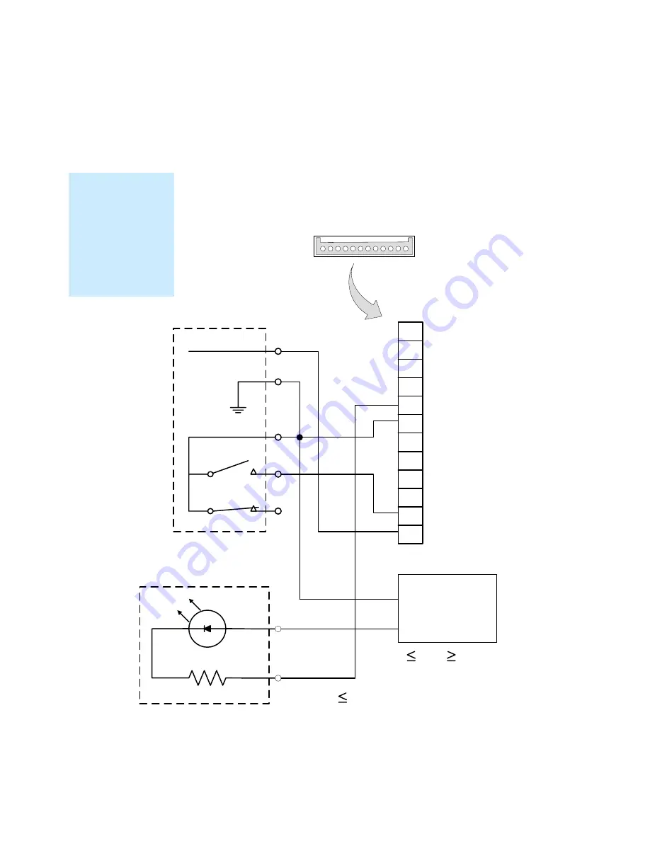
Figure 5 shows a typical sensor/indicator connection to the digital I/Os.
12-24 Vdc
NO
NC
Motion Sensor
Tag Detection Indicator
12
Digital Output Common
1
Digital Input Common for DIN1/DIN2
2
DIN1 (Digital Input 1)
11
DOUT4 (Digital Output 4)
3
DIN2 (Digital Input 2)
10
DOUT3 (Digital Output 3)
4
Digital Input Common for DIN3/DIN4
9
DOUT2 (Digital Output 2)
5
DIN3 (Digital Input 3)
8
DOUT1 (Digital Output 1)
7
Digital Output Common
6
DIN4 (Digital Input 4)
External
DC Supply
(User Supplied)
(V
DC
)
_
+
R
S
5V
V
DC
40V
(V
DC
)
2
/R
S
1W
IN
finity
610 Digital I/O
12
1
Figure 5
Example Motion Detector and Indicator connected to the Digital I/O
External DIO
Interface Module
An external DIO
interface module is
available for the
INfinity 610. See
the Appendix in this
User’s Guide for
more information.
Summary of Contents for INfinty 610
Page 1: ......
Page 8: ...Contents vi INfinity 610 User s Guide This page intentionally left blank ...
Page 75: ...1 2 3 4 5 6 7 8 9 Reader Configuration Tool INfinity 610 User s Guide 67 ...
Page 107: ...INfinity 610 User s Guide This page intentionally left blank ...
Page 108: ...INfinity 610 User s Guide ...


