1
1
WARNINGS
* The appliance is not intended for use by
young children or infirm persons without
supervision. Young children should be su-
pervised to ensure they do not play with the
appliance.
* The air sucked can’t be conveyed through
or into a duct used to let out fumes from
appliances fed by energy other than electric
power (eg. centralized heating, radiators,
water-heaters, etc.).
* To evacuate the air outlet, please comply
with the pertaining rules given by competent
authorities.
The cooker hood, when evacuating the sucked
air, could generate a negative pressure in the
room- which can’t exceed the limit of 0.04
mbar, in order to avoid the suck of exhausts
deriving from the heat-source.
Therefore the room should be provided with
air-intakes to allow a constant flow of fresh
air.
* When performing the electrical connections
on the appliance, please make sure that them
current-tap is provided with earth connection
and that voltage values correspond to those
indicated on the label placed inside the ap-
pliance itself.
* Please disconnect the appliance from power
mains, before carrying out any cleaning or
maintenance operation.
If the appliance is not equipped with a non-
separable flexible cable and plug, or with an-
other device ensuring omnipolar disconnec-
tion from the mains, with an opening distance
between the contacts of at least 3 mm, then
such disconnecting devices must be provided
in the fixed installation.
If the appliance is equipped with a power cord
and a plug, it shall be placed in such a way
that the plug can be reached easily.
* The use of materials which can burst into
flames (flambé) should be avoided in close
proximity of the appliance.
When frying, please pay particular attention
to fire risk due to oil and grease.
Being highly inflammable, fried oil is espe-
cially dangerous. Do not use uncovered elec-
tric grills.
In order to avoid possible fire risk, all in-
structions for grease-filter cleaning and for
removing eventual grease deposits should be
strictly followed.
* Two persons are needed for the installation
of this product.
12
USE
INSTALLATION
To install the product is necessary to make
a countertop minimum depth of at least 220
mm up to a maximum of 400 mm. For great-
er depths it is necessary to ask the special
KIT with mounting brackets for ceiling depth
from 400mm to 580mm.
Attention: If a remote motor is installed
in the same compartment as products
SLT955/SLT956, check the overall dimen-
sions of the remote motor.
You can choose the side of the hood from
which to run off the sucked air; there are air
outlets of rectangular shape on three sides
of the hood.
After choosing the best location, set up the
channel, the supply provided includes an air
outlet flange of rectangular shape 230x80mm
to be installed on the chosen outlet. Leave
closed the air exhaust holes are not used.
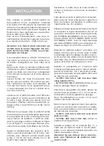
There is also a fitting included, that allows
the use of tubes with a diameter equal to 150
mm (see fig. 1), if you plan to create a circular
air outlet duct.
Identify a reference point compared to the
exact centre for hood installation in the solid
ceiling. Then mark out the area for the holes
to be drilled, at the points shown in figure
2 for the item SLT955 or fig. 3 for the item
SLT956.
Make the holes in the solid ceiling, using a
suitable 8 mm helical drill bit and insert the
plugs provided. It is sufficient to drill the
outer holes shown in figure 2 or figure 3; the
inner holes can be drilled after installing the
hood.
Adjust the excursion of the fixing brackets
according to the depth of the niche; min.
220mm, max. 400mm as, shown in Fig. 4.
Tighten strongly the fastening screws of the
brackets immediately after you placed them
into position.
Place the cooker hood in an established area
and fix it with the screws supplied (see fig. 5).
Perform the holes into the ceiling in corre-
spondence of the central holes of the brack-
ets and fix definitively the product by apply-
ing the remaining screws.
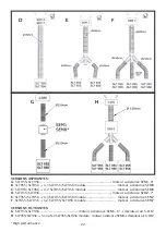
Make the electrical connection (see fig. 6)
and connect the air discharge pipe following
the instructions given in the related section
DUCTING SYSTEMS.
If installing an
SLT 955 MODUL LIGHT or
SLT 956 MODUL LIGHT, connect the elec-
trical wire of the MODUL LIGHT hood to the
connectors shown in figure 6 on SLT955 or
SLT956.
Install the plasterboard sheet making sure
that it fits perfectly to the metal edge of the
hood (Fig 12).
The dimensions of the hole to make in the
plasterboard are:
- SLT955: 502 mm X 502 mm with two
curved sides R551,
- SLT956: 982 mm X 222 mm, use the drill-
ing template provided.
Use the 3.5 x 22 screws supplied to fix the
plasterboard to the cooker hood and insert
them using the appropriate hole template.
We recommend at least 12 screws to obtain
a good fixation.
In case the hood is provided with an internal
panel be covered in plasterboard, wood or
other material, make a sheet of the following
dimensions:
- SLT955: 448 mm X 448 mm with R524 on
the corners,
- SLT956: 928 mm X 168 mm, use the drill-
ing template supplied.
Install the sheet to the panel (fig. 7), using
the screws provided in the case of plaster-
board or using the appropriate adhesive for
the type of material to be secured.
Caution: Do not use screws longer than the
panel thickness, maximum 3.5 x 22.
The product is not equipped with the duction
motor, therefore it must be coupled to a suc-
tion unit (remote motor) of the same manu-
facturer.
Summary of Contents for SLT955
Page 1: ......
Page 13: ...10 CONTENTS Warnings Use Installation Panel opening Ducting systems Working Maintenance EN ...
Page 63: ...59 1 4 5 6 2 3 ...
Page 64: ...60 7 8 9 10 12 11 ...
Page 65: ...52 13 14 15 61 13 14 15 52 13 14 15 ...
Page 66: ...62 ...


