51
ПРЕДУПРЕЖДЕНИЯ
* Дети, лица, не имеющие опыта работы с
прибором или имеющие физические и
умственные отклонения, не допускаются
к работе с прибором. Проследите, чтобы
дети не играли с прибором и с его
электронными компонентами.
* Выходящий воздух не должен попадать в
воздуховоды, используемые для отвода
дыма от приборов, которые потребляют
источники
энергии,
отличные
от
электричества (системы центрального
отопления,
нагреватели
воды,
калориферы и т.д.)
* Для вывода воздуха наружу необходимо
соблюдать существующие в каждой
стране правила.
При выводе воздуха вытяжка может
создать
отрицательное
давление
в
помещении. Оно не должно превышать
0,04 микробар во избежание обратного
захода выводимого газа
из
источника
отопления.
Поэтому,
необходимо
предусмотреть в помещении воздушные
отверстия, через которые будет постоянно
поступать свежий воздух.
* При подключении прибора к электросети
убедитесь в том, чтобы розетка имела
заземление, а также проверьте
соответствие напряжения розетки и
прибора.
* Прежде чем приступать к какой-либо
операции по чистке или уходу за
прибором, необходимо отключить его от
электросети.
Если вытяжка снабжена вилкой,
подключите
вытяжку к штепсельному разъему. Он
должен
отвечать
действующим
правилам и
должен
быть
расположен в
легкодоступном
месте. Включить в розетку можно после
установки. Если же вытяжка не снабжена
вилкой (прямого подключения к сети), или
штепсельный разъем не расположен в
доступном месте, также и после установки,
то используйте надлежащий двухполюсный
выключатель, обеспечивающий полное
размыкание сети при возникновении
условий перенапряжения 3-й категории, с
расстоянием
между
разомкнутыми
контактами не менее 3 мм.
* Избегайте
использования
легковоспла-
меняющихся материалов для поджига
(фламбе), в непосредственной близости от
прибора. При жарке продуктов проявляйте
особую осторожность во избежание пожара,
который могут вызвать масла и жиры.
Повторно используемое масло для жарки
является
наиболее
опасным
в
возникновении пожара. Не используйте
открытый электрический гриль. Во
избежание
возникновения
пожара
необходимо
внимательно
выполнять
инструкции по очистке жирового фильтра и
своевременно удалять скопившийся жир с
прибора.
* Данную вытяжку должны устанавливать два
человека.
12
ИСПОЛЬЗОВАНИЕ
INSTALLATION
To install the product is necessary to make
a countertop minimum depth of at least 220
mm up to a maximum of 400 mm. For great-
er depths it is necessary to ask the special
KIT with mounting brackets for ceiling depth
from 400mm to 580mm.
Attention: If a remote motor is installed
in the same compartment as products
SLT955/SLT956, check the overall dimen-
sions of the remote motor.
You can choose the side of the hood from
which to run off the sucked air; there are air
outlets of rectangular shape on three sides
of the hood.
After choosing the best location, set up the
channel, the supply provided includes an air
outlet flange of rectangular shape 230x80mm
to be installed on the chosen outlet. Leave
closed the air exhaust holes are not used.
There is also a fitting included, that allows
the use of tubes with a diameter equal to 150
mm (see fig. 1), if you plan to create a circular
air outlet duct.
Identify a reference point compared to the
exact centre for hood installation in the solid
ceiling. Then mark out the area for the holes
to be drilled, at the points shown in figure
2 for the item SLT955 or fig. 3 for the item
SLT956.
Make the holes in the solid ceiling, using a
suitable 8 mm helical drill bit and insert the
plugs provided. It is sufficient to drill the
outer holes shown in figure 2 or figure 3; the
inner holes can be drilled after installing the
hood.
Adjust the excursion of the fixing brackets
according to the depth of the niche; min.
220mm, max. 400mm as, shown in Fig. 4.
Tighten strongly the fastening screws of the
brackets immediately after you placed them
into position.
Place the cooker hood in an established area
and fix it with the screws supplied (see fig. 5).
Perform the holes into the ceiling in corre-
spondence of the central holes of the brack-
ets and fix definitively the product by apply-
ing the remaining screws.
Make the electrical connection (see fig. 6)
and connect the air discharge pipe following
the instructions given in the related section
DUCTING SYSTEMS.
If installing an
SLT 955 MODUL LIGHT or
SLT 956 MODUL LIGHT, connect the elec-
trical wire of the MODUL LIGHT hood to the
connectors shown in figure 6 on SLT955 or
SLT956.
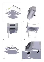
Install the plasterboard sheet making sure
that it fits perfectly to the metal edge of the
hood (Fig 12).
The dimensions of the hole to make in the
plasterboard are:
- SLT955: 502 mm X 502 mm with two
curved sides R551,
- SLT956: 982 mm X 222 mm, use the drill-
ing template provided.
Use the 3.5 x 22 screws supplied to fix the
plasterboard to the cooker hood and insert
them using the appropriate hole template.
We recommend at least 12 screws to obtain
a good fixation.
In case the hood is provided with an internal
panel be covered in plasterboard, wood or
other material, make a sheet of the following
dimensions:
- SLT955: 448 mm X 448 mm with R524 on
the corners,
- SLT956: 928 mm X 168 mm, use the drill-
ing template supplied.
Install the sheet to the panel (fig. 7), using
the screws provided in the case of plaster-
board or using the appropriate adhesive for
the type of material to be secured.
Caution: Do not use screws longer than the
panel thickness, maximum 3.5 x 22.
Устройство не оснащено двигателем,
поэтому его необходимо подсоединить к
всасывающему устройству. Использовать
следует удаленный двигатель того же
производителя.
Summary of Contents for SLT955
Page 1: ......
Page 13: ...10 CONTENTS Warnings Use Installation Panel opening Ducting systems Working Maintenance EN ...
Page 63: ...59 1 4 5 6 2 3 ...
Page 64: ...60 7 8 9 10 12 11 ...
Page 65: ...52 13 14 15 61 13 14 15 52 13 14 15 ...
Page 66: ...62 ...

