Sirona Dental Systems GmbH
3 Checking the Supply Lines
59 58 470 D 3370
D 3370.031.01.10.02
7
båÖäáëÜ
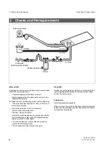
Supply through the floor
•
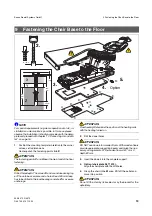
Unfold the mounting template.
•
Cut out the installation field.
•
Lay the template over lead ends on the site and check
the distances of the installation field from the walls in
accordance with the practice.
•
Then check the installation for the following:
1.
The top edges of the corner valves for air and water
must not project more than 60 mm above the upper sur-
face of the finished floor.
2.
The suction and drain pipes must finish flush with the
upper surface of the floor. (Permissible deviation:
+5 mm).
Internal diameter for both pipes: 36.5 mm
∅
.
3.
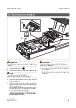
The electric leads must project by at least 500 mm.
Supply above the floor
Supply tube ends, corner valves and leads are routed as
shown (for details see
Mounting Template
).
For the connection, the retrofit kit for installation above
ground 33 17 265 is required.
ATTENTION
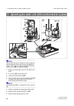
Clean out the air and water pipes (metal chips!).
3 Checking the Supply Lines
Supply through the floor
Supply above the floor
Installation template
Solder fittings: 3/8" ext. thread
ca. 250mm
ca. 200mm
ca. 500mm
min. 500mm
max. 60 mm
3/8“
Ventilation
1.
2.
3.
0 – 5 mm
B
a
s
e
H
e
a
d

