Sirona Dental Systems GmbH
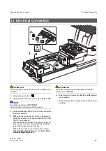
12 Electrical Connection
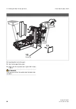
59 58 470 D 3370
D 3370.031.01.10.02
17
båÖäáëÜ
ATTENTION
Switch OFF power from the main switch for the electrical in-
stallation.
1.
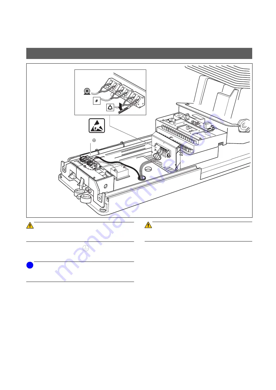
Connect power line: N, L,
2.
Connect control leads of suction pump to
X4.47
and
49
.
NOTE
i
Connecting technique for
X2, X3, X4
:
First press with a screwdriver, and then plug in.
3.
Connect call leads to
X2.1
and
2
.
Only the push-button
function is possible.
4.
X3.3
and
4
are terminal points for key # (for example,
composite function of the ceiling model SIROLUX FAN-
TASTIC, when present).
With the SIROLUX FANTASTIC ceiling model, two ca-
bles have to be laid from the ceiling to the installation
tube in the connection area of the chair.
Note setting as switch or push-button (momentary).
(See
Operating Instructions
, chapter ”
Basic Work-
station Settings, Mode Key”
).
ATTENTION
The control voltages connected to
X2
,
X3
and
X4
may
amount to max.
230V
,
6A
.
5.
Fasten the control cables from
X2
,
X3
and
X4
together
with a cable tie.
•
Switch ON power from the main switch for the electrical
installation.
12 Electrical Connection
1
2
3
X3
X2
X4
4
49
47
L
N
1.
2.
3.
4.
5.

