59 38 399 D3352
4 – 48
D3352.076.01.13.02
07.2008
4.3 Adjusting the panoramic X-ray unit
Tabs 4
– The shadow of the center needle, the needle image and the auxil-
iary line must be coincident and located behind each other.
A tolerance (offset of needle from the central auxiliary line) of
± 0.75
mm is admissible (A).
– Distance A1 must be 88.6
± 1
mm (A).
– Distances A2 must be identical, each being 44.3
± 0.5
mm (A).
– A white border surrounding the image on all sides must be visible
(B).
NOTE
i
If one of these criteria is not fulfilled
(C)
, the pan symmetry must be adjusted.
Making the unit ready for exposure
NOTE
i
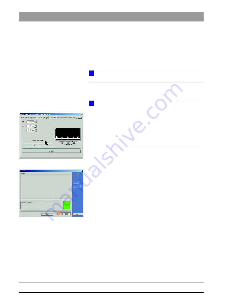
The default values for S1, S2 and S3 were automatically determined by
SIDEXIS based on the exposure and entered in the text boxes of the menu.
For manual adjustment, the values displayed at this position in the text boxes
of the menu can be overwritten (see page 4-21).
First continue with the automatic adjustment. Manual determination of the ad-
justment values is required only if you fail to reach your goal via automatic ad-
justment (see page 4-20).
5.
Make SIDEXIS XG ready for exposure:
Click
IMAGE
ACQUISITION
SIDEXIS screen
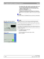
The exposure dialog box showing the exposure status
appears in SIDEXIS.
Summary of Contents for ORTHOPHOS XG 3 DS
Page 4: ......
Page 9: ...ORTHOPHOS XG 1General information...
Page 12: ...59 38 399 D3352 1 4 D3352 076 01 13 02 07 2008 Tab1...
Page 59: ...ORTHOPHOS XG 2 Messages...
Page 124: ...59 38 399 D3352 2 66 D3352 076 01 13 02 07 2008 2 6 List of available service routines Tab 2...
Page 125: ...ORTHOPHOS XG 3 Troubleshooting...
Page 153: ...ORTHOPHOS XG 4 Adjustment...
Page 269: ...ORTHOPHOS XG 5 Service routines...
Page 433: ...ORTHOPHOS XG 6 Repair...
Page 436: ...59 38 399 D3352 6 4 D3352 076 01 13 02 07 2008 Tab6...
Page 530: ...59 38 399 D3352 6 98 D3352 076 01 13 02 07 2008 6 21 Replacing cables Tabs 6...
Page 531: ...ORTHOPHOS XG 7 Maintenance...
Page 577: ...b 59 38 399 D3352 D3352 076 01 13 02 07 2008...


