59 38 399 D3352
4 – 62
D3352.076.01.13.02
07.2008
4.4 Adjusting the cephalometer (XG
Plus
/ XG 5, if ceph is installed) Tabs 4
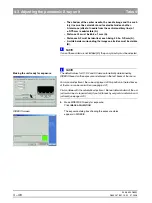
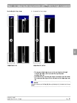
– The vertical pin must be horizontally centered in the exposed im-
age area A. A slight vertical offset of the grid is permissible.
– A uniform white border surrounding the image on all sides must
be visible A.
– Distance S3 must be approx. 60mm.
NOTE
i
If these criteria are not fulfilled
(B)
, the ceph primary diaphragm must be
adjusted.
NOTE
i
If S3 is > 70 mm, then contact the Sirona Customer Service Center: Phone: 0
62 51/16 - 16 16
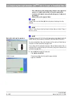
Making the unit ready for exposure
NOTE
i
The default values for S1, S2, S3 and S4 were automatically determined by SI-
DEXIS based on the exposure and entered in the text boxes of the menu.
For manual adjustment, the values displayed at this position in the text boxes
of the menu can be overwritten (see page 4-67).
First continue with the automatic adjustment. Manual determination of the ad-
justment values is required only if you fail to reach your goal via automatic ad-
justment (see page 4-66).
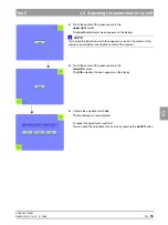
5.
Make SIDEXIS XG ready for exposure:
Click
IMAGE
ACQUISITION
SIDEXIS screen
The exposure dialog box showing the exposure status
appears in SIDEXIS.
Summary of Contents for ORTHOPHOS XG 3 DS
Page 4: ......
Page 9: ...ORTHOPHOS XG 1General information...
Page 12: ...59 38 399 D3352 1 4 D3352 076 01 13 02 07 2008 Tab1...
Page 59: ...ORTHOPHOS XG 2 Messages...
Page 124: ...59 38 399 D3352 2 66 D3352 076 01 13 02 07 2008 2 6 List of available service routines Tab 2...
Page 125: ...ORTHOPHOS XG 3 Troubleshooting...
Page 153: ...ORTHOPHOS XG 4 Adjustment...
Page 269: ...ORTHOPHOS XG 5 Service routines...
Page 433: ...ORTHOPHOS XG 6 Repair...
Page 436: ...59 38 399 D3352 6 4 D3352 076 01 13 02 07 2008 Tab6...
Page 530: ...59 38 399 D3352 6 98 D3352 076 01 13 02 07 2008 6 21 Replacing cables Tabs 6...
Page 531: ...ORTHOPHOS XG 7 Maintenance...
Page 577: ...b 59 38 399 D3352 D3352 076 01 13 02 07 2008...

