båÖäáëÜ
59 38 399 D3352
D3352.076.01.13.02
07.2008
4 – 77
Tab 4 4.4 Adjusting the cephalometer (XG
Plus
/ XG 5, if ceph is installed)
4.
4
Evaluating the X-ray image
12.
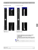
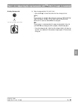
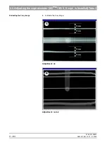
Evaluate the X-ray image:
– The exposed diaphragm area must lie centered and straight
in the image field as well as inside the superimposed
auxiliary lines (A).
– A white border surrounding the image on all sides must be visible.
The maximum density must lie in the center of the diaphragm area
(A).
NOTE
i
If this criterion is not yet fulfilled, repeat the adjustment procedure starting with
step 5.
If you do not reach your goal via automatic adjustment, repeat the adjustment
procedure with manually determined adjustment values (see page 4-79).
Adjustment: ok
A
Summary of Contents for ORTHOPHOS XG 3 DS
Page 4: ......
Page 9: ...ORTHOPHOS XG 1General information...
Page 12: ...59 38 399 D3352 1 4 D3352 076 01 13 02 07 2008 Tab1...
Page 59: ...ORTHOPHOS XG 2 Messages...
Page 124: ...59 38 399 D3352 2 66 D3352 076 01 13 02 07 2008 2 6 List of available service routines Tab 2...
Page 125: ...ORTHOPHOS XG 3 Troubleshooting...
Page 153: ...ORTHOPHOS XG 4 Adjustment...
Page 269: ...ORTHOPHOS XG 5 Service routines...
Page 433: ...ORTHOPHOS XG 6 Repair...
Page 436: ...59 38 399 D3352 6 4 D3352 076 01 13 02 07 2008 Tab6...
Page 530: ...59 38 399 D3352 6 98 D3352 076 01 13 02 07 2008 6 21 Replacing cables Tabs 6...
Page 531: ...ORTHOPHOS XG 7 Maintenance...
Page 577: ...b 59 38 399 D3352 D3352 076 01 13 02 07 2008...


