59 38 399 D3352
3 – 10
D3352.076.01.13.02
07.2008
3.2 Check the CAN bus
Tab 3
3.2.2
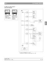
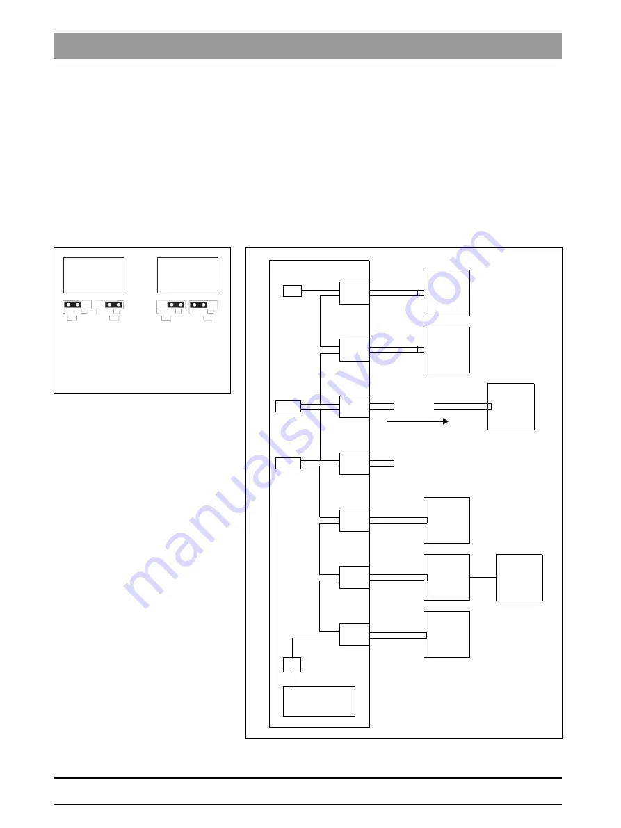
Jumper positions in the CAN bus
The jumpers are located on board DX1 at sockets X302, X303, X306, X307,
X309, X500 and X503 (see also wiring diagrams).
If a cable is plugged into the socket, the corresponding jumpers must be set
to the outer position. If no cable is plugged in, the jumpers must be set to the
inner position.
If a jumper is not set to the inner position with a cable plugged in, the CAN bus
is interrupted at this location. Modules located behind this location can no
longer be connected to the CAN bus, and therefore do not function.
Up to unit hardware version AG
*
Connector not plugged in for XG 3/3 PPE,
Jumper must be connected to socket X306 inside for XG 3 / 3 PPE
Socket,
e.g. X500
Socket,
e.g. X309
Jumper outside
Jumper inside
Module con-
nected, i.e. con-
nector plugged in
Module not con-
nected, i.e. con-
nector not
plugged in
DX11
PowerPC
RS
RS
X503
SUB_D
X500
SUB_D
X309
RJ45
X307
SUB_D
X306
RJ45
X303
RJ45
X302
RJ45
DX81
Ceph
sensor
DX81
Pan
sensor
DX61*
Dia-
phragm
DX41
Inter-
face
DX7
Display
DX91
Ceph
sensor
Jumper
Jumper
Optional
connection
DX42
Remote
control
DX1
Summary of Contents for ORTHOPHOS XG 3 DS
Page 4: ......
Page 9: ...ORTHOPHOS XG 1General information...
Page 12: ...59 38 399 D3352 1 4 D3352 076 01 13 02 07 2008 Tab1...
Page 59: ...ORTHOPHOS XG 2 Messages...
Page 124: ...59 38 399 D3352 2 66 D3352 076 01 13 02 07 2008 2 6 List of available service routines Tab 2...
Page 125: ...ORTHOPHOS XG 3 Troubleshooting...
Page 153: ...ORTHOPHOS XG 4 Adjustment...
Page 269: ...ORTHOPHOS XG 5 Service routines...
Page 433: ...ORTHOPHOS XG 6 Repair...
Page 436: ...59 38 399 D3352 6 4 D3352 076 01 13 02 07 2008 Tab6...
Page 530: ...59 38 399 D3352 6 98 D3352 076 01 13 02 07 2008 6 21 Replacing cables Tabs 6...
Page 531: ...ORTHOPHOS XG 7 Maintenance...
Page 577: ...b 59 38 399 D3352 D3352 076 01 13 02 07 2008...


