59 38 399 D3352
6 – 24
D3352.076.01.13.02
07.2008
6.6 Replacing the control panel
Tabs 6
6.6
Replacing the control panel
Removing the user interface
z
Remove the user interface (see page 6-21).
Removing the defective control panel
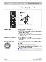
1.
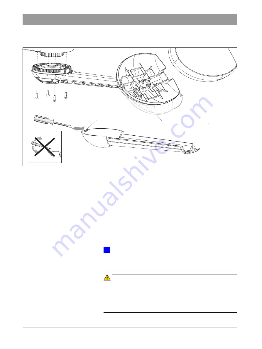
Swing folding mechanism
A
for the user interface all the way up. This
makes it easier to remove the cover.
2.
Press into slit
B
of the housing cover with a screwdriver
(do not pry!)
and
remove the cover.
3.
Detach cables
L9
and
L10
from the strain reliefs.
4.
Rotate the control panel to the center position and loosen the four screws
C
.
z
Pull the cables out of the control panel and remove the panel.
Installing the new control panel
z
To install the control panel and the user interface, follow the procedure for
removing them in reverse order.
NOTE
i
Don't forget to plug connectors X102 and X103 back into board
DX7/DX71, lay the cables in their original positions and reattach the strain re-
liefs (see "Laying cables when replacing the control panel" on page 6-25).
ATTENTION: What to do after replacement?
– Check the user interface for correct functioning as well as the
function of the display elements. (After the unit is switched ON
all of the display elements must light up briefly!)
– No further action is required.
A
B
C
2.
1.
4.
Summary of Contents for ORTHOPHOS XG 3 DS
Page 4: ......
Page 9: ...ORTHOPHOS XG 1General information...
Page 12: ...59 38 399 D3352 1 4 D3352 076 01 13 02 07 2008 Tab1...
Page 59: ...ORTHOPHOS XG 2 Messages...
Page 124: ...59 38 399 D3352 2 66 D3352 076 01 13 02 07 2008 2 6 List of available service routines Tab 2...
Page 125: ...ORTHOPHOS XG 3 Troubleshooting...
Page 153: ...ORTHOPHOS XG 4 Adjustment...
Page 269: ...ORTHOPHOS XG 5 Service routines...
Page 433: ...ORTHOPHOS XG 6 Repair...
Page 436: ...59 38 399 D3352 6 4 D3352 076 01 13 02 07 2008 Tab6...
Page 530: ...59 38 399 D3352 6 98 D3352 076 01 13 02 07 2008 6 21 Replacing cables Tabs 6...
Page 531: ...ORTHOPHOS XG 7 Maintenance...
Page 577: ...b 59 38 399 D3352 D3352 076 01 13 02 07 2008...


