61 77 476 D 3495
20
D 3495
.
201.01.02
.
02
08.2007
5
Installation
Sirona Dental Systems GmbH
Installation of the additional protective ground wire
Operating Instructions and Installation
XIOS USB
5.2
Installation of the additional protective
ground wire
Preparation
9
All running programs have been terminated.
9
The PC and all connected components have been switched off.
9
The power cord has been removed.
1.
Put on an ESD wrist band or discharge your body by touching the
equipotential bonding conductor.
2.
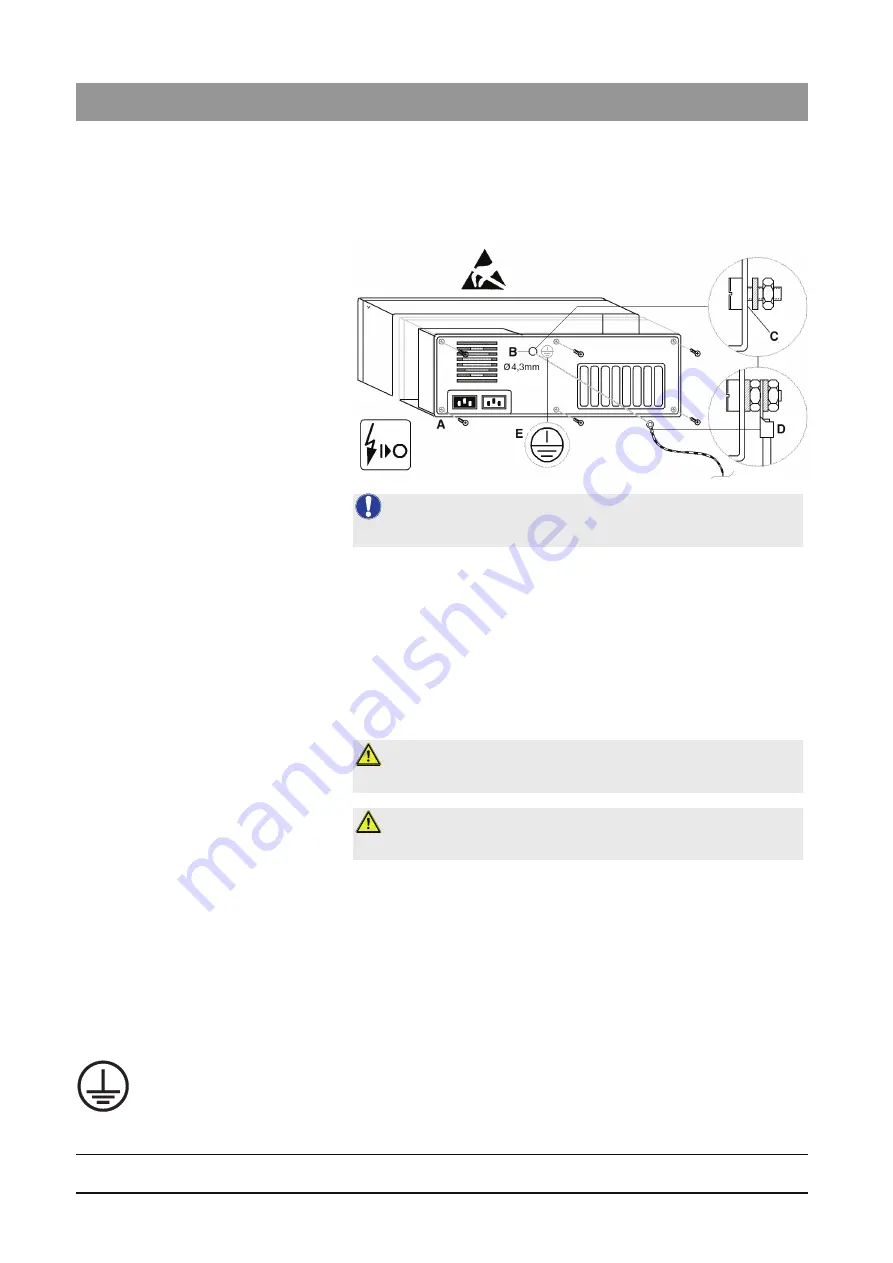
Undo the screws of the PC casing (
A
) (see the PC operator's manual)
and remove the cover of the PC.
Drilling
1.
Find a location to connect the protective ground wire on the rear side of
the metal casing frame (
B
) that is readily accessible from the inside and
from the outside.
2.
Drill a hole with a suitable diameter for an M4 screw at this location (
B
).
3.
Remove any paint around the drill hole (
C
) to achieve a good metal
contact.
Installation
1.
Fasten the enclosed connecting screw firmly with a toothed lock washer
and nut.
2.
Screw down the protective ground wire (
D
) as shown.
3.
Affix the attached label (
E
) next to the protective ground wire connection.
4.
Connect the protective ground wire to the equipotential bonding
conductor.
NOTE:
The illustration is a case example.
CAUTION: Risk of damage
Be careful not to damage any parts of the PC when drilling!
CAUTION: Risk of short circuit
Make sure that no swarf get inside the PC when drilling.


