SIRS NAVIGATION LTD
COMPONENT MAINTENANCE MANUAL
The procedure detailed below must be followed if ‘magnetic correction’ problems are
identified.
NOTE: Before you do these tests, refer to the ‘Installation Instructions’.
a)
Remove the compass from the aircraft.
b)
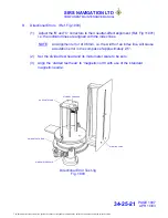
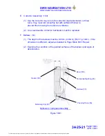
Adjust the magnetic correctors to their neutral-effect alignment – (Ref. Fig.11001).
c)
Put the compass, on a non-magnetic stand away from magnetic sources.
d)
Align the compass to North.
e)
Turn the ‘North-South’ corrector shaft clockwise, with the corrector key (220).
Monitor the compass card movement. It must be between 25 and 35
°
.
f)
Turn the ‘North-South’ corrector shaft counter-clockwise, with the corrector key.
Monitor the compass card movement. It must be between 25 and 35
°
and of
equal value to that recorded in paragraph e).
g)
Turn the magnetic correctors, with the corrector key, to their neutral-effect
alignment – (Ref. Fig.11001).
h)
Align the compass to a South heading and test the maximum correction value, as
detailed in paragraphs e) to g).
i)
Follow this test procedure for the East and West headings. Engage and turn the
‘corrector key’ in the ‘East-West’ correction hole.
j)
Replace the ‘corrector assembly’ (160) if the test results are not satisfactory.
CORRECTOR LOCATION
Figure 1002
PAGE 1004
APR 10/03
34-25-21
The document reference is online, please check the correspondence between the online documentation and the printed version.


