SIRS NAVIGATION LTD
COMPONENT MAINTENANCE MANUAL
B. Electrical
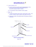
(1) Remove the cap (250) and lamp (240) from the lamp housing assembly (230).
(2) Test the insulation resistance between the two connecting pins of the ‘lamp
housing’. The value must not be less than 20 megohms at 500 V D.C.
(3) Replace the lamp and cap to the lamp housing assembly.
(4) Test the electrical resistance between the two connecting pins of the lamp
housing . The correct value is detailed in table 5001 Page Block 5002.
NOTE:
Do the test that follows in a dark room.
(5) Connect the lead and socket assembly (260) to the connecting pins on the lamp
housing assembly. Connect the 5 or 28V D.C. electrical supply to the lead.
(6) Make sure that the light comes on.
C. Temperature
(1) Put the compass in an environmental chamber and decrease the temperature to
-40°C
±
2°C for three hours in the refrigerator.
(2) Remove the compass from the environmental chamber and let the temperature
increase to ambient conditions.
(3) Examine the compass for signs of cracks, fluid leakage, discoloration or air
bubbles within the compass.
(4) Put the compass in an environmental chamber and increase the temperature
+85°C
±
2°C at an approximate rate of 15°C per hour. Keep the compass at this
temperature for one hour.
(5) Remove the compass from the environmental chamber and let the temperature
decrease to ambient conditions.
(6) Examine the compass for signs of cracks, fluid leakage, discoloration or air
bubbles in the compass.
PAGE 1006
APR 10/03
34-25-21
The document reference is online, please check the correspondence between the online documentation and the printed version.


