SIRS NAVIGATION LTD
COMPONENT MAINTENANCE MANUAL
D.
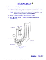
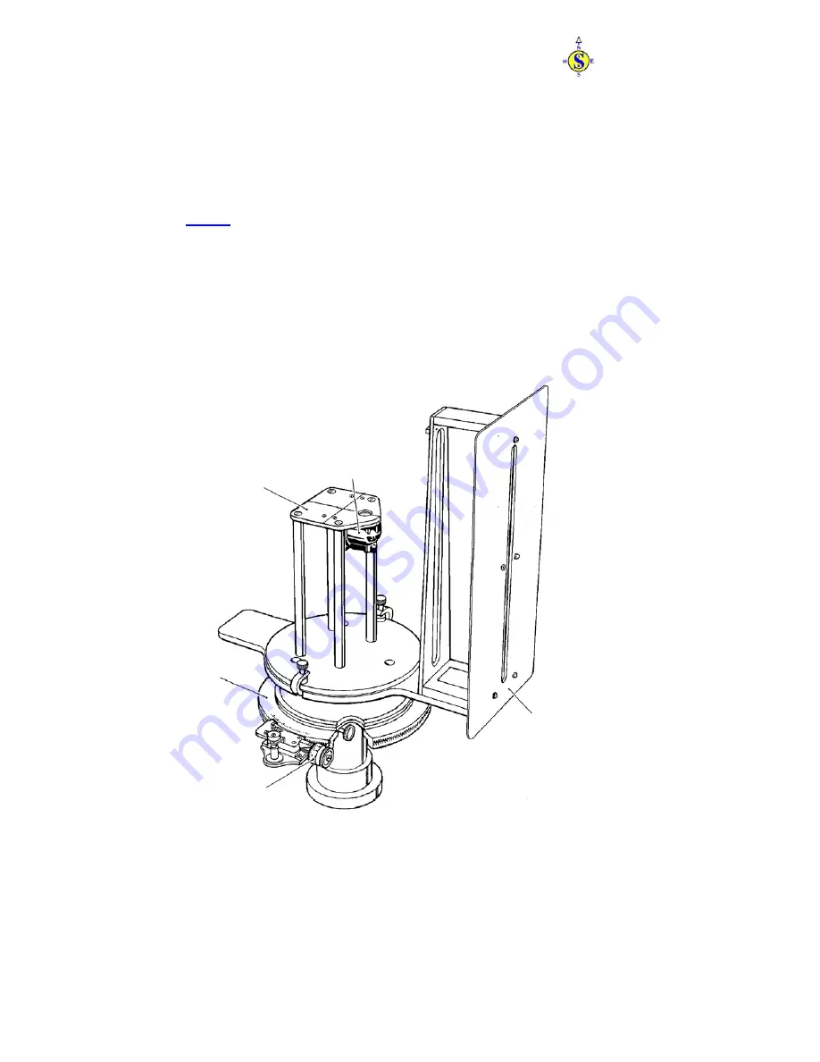
Directional Errors (Ref. Fig.1003)
(1) Adjust the 'B' and 'C' correctors to their neutral-effect alignment (Ref. Fig 11001)
i.e. the indicator lines are aligned with the index lines.
NOTE: An Alignment error of 0.5mm, i.e. the width of an index line, will cause
a deviation error in the compass of approximately 2.5°.
(2) Set the divided test head and its micrometer scale to be zero.
(3) Align the ‘divided test head’ to ‘magnetic north’ with use of the ‘standard
magnetic needle’.
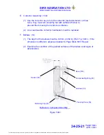
Directional Error Test Jig
Fig. 1003
STANDBY COMPASS
SUPPORT STAND
DIVIDED TEST HEAD
SIGHTING VANE
MICROMETER SCALE
PAGE 1007
APR 10/03
34-25-21
The document reference is online, please check the correspondence between the online documentation and the printed version.


