SIRS NAVIGATION LTD
COMPONENT MAINTENANCE MANUAL
D. Stem Assembly (80) and Compass Card Assembly (130)
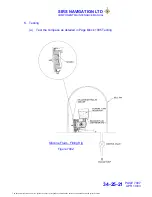
(1) Assemble the ‘stem assembly’ (80) to the compass bowl (180) with two
non-magnetic screws (90).
(2) Assemble the sapphire checking plate 3256 LMT to the the compass bowl
with the two knurled screws.
(3) Light up the compass bowl. Move the vertical stem of the ‘stem assembly’ to
align the ‘bearing cup’ with the centre of the sapphire checking plate.
(4) Remove sapphire checking plate.
(5) Remove the two screws, that hold the bracket of the stem assembly to the
compass bowl and remove the stem assembly.
(6) Assemble the compass card assembly (130) to the stem assembly (80).
(7) Assemble the complete assembly into the bowl (180) with two screws (90).
(8) The compass card assembly must rotate freely within the bowl.
E. Bellows
Assembly
CAUTION:
DO NOT DAMAGE THE GASKET (60) WITH SHARP EDGES OF
THE ASSEMBLY COMPONENTS.
NOTE: The gasket (60) must be immersed in silicone fluid for 1 hour before
assembly.
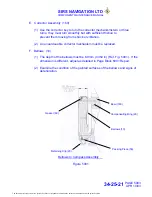
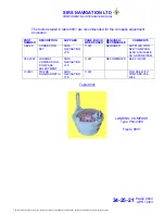
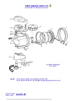
(1) Assemble the compensation ring (70) and bellows gasket (60) to the rear of
the compass bowl (180), (Ref. Fig 5001).
(2) Assemble the bellows (10) to the rear of the compass bowl.
(3) Assemble the retaining clip (20) to the compass bowl.
(4) Assemble the packing piece (50) under the ends of the retaining clip and
tighten the assembly with the screw (30) and nut (40).
NOTE: The gap between the ends of the retaining clip (20) must be not less
than 0.8mm (1/32”) after the screw (30) is tightened.
PAGE 7004
APR 10/03
34-25-21
The document reference is online, please check the correspondence between the online documentation and the printed version.

