background image

P62

-50-

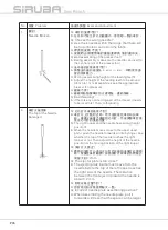
Turn on the power of the sewing machine; 

the power indicator      of the sensor should be 
green, and the sensor indicator      should be 
orange. Both the indicators remain lit. If one of 
them is extinguished, it needs to parallelize 
the sensors and the working table    , and then 

adjust the front-rear position of the sensor     
based on the demand until both indicators 
remain lit. Then, tighten the screw    . 

For sewing test, the indicator     (orange) 

would be extinguished when putting the 
sewing material. It means the sewing material 
is detected. The indicator     (orange) would be 
lit again when r emoving the sewing material. 

 If the sensitivity of the sensor has sort of 

inaccuracy, keep pressing the button     until 
both the indicators are lit for showing the 
material is sensed successfully. 

Repeat the above procedure several times, 

if it normal means the adjustment is done. 
Hence, the sewing can be activated. 

 The sensor is based on the principle of 

photoelectric reflection, and it may cause error 
by the following fabric (Note 1). It is suggested 
to turn off the sensor. 

Note 1 : Fabric easy to cause errors

 mesh fabric

 Reflective fabric

Note 2 : All the adjustment is finis hed before 

correctly leaving the factory. 

Note 3: Must use the light-color fabric to 

adjust the electric eye; otherwise, it 
will cause errors with using the dark-
color fabric for that the contrast of 
the electric eye would be too high. 

打開 縫紉 機電 源,此 時電 眼感 測器 之

電 源指 示燈    為綠 燈, 感應 狀 態 指 示燈  
為 橙燈, 且兩 燈為 恆亮 狀態 , 若此 時 電源
指示 燈    或 感應 狀態指 示燈   之 任何 一 燈
號呈 現滅 的狀 態,則 需調 整 電 眼感 測器 與
工作平 台    呈 平行 方向 , 再 依需 求調 整 整
電 眼感 測器    之前 後位置 ,直 至兩 燈 為恆
亮狀 態, 再鎖 緊固 定螺 絲    。

以待 縫製 物測 試, 放入 縫製 物 時, 感

應狀態 指示 燈    

(

橙燈

)

為 滅 的狀 態 , 表 示

目前 已檢測 到縫 製物 ;移 除 縫 製物 時, 感
應 狀態 指示 燈    

(

橙燈

)

會 再度 亮 起。


若電 眼感測 器靈 敏度 有些 許 誤 差 ,可

按 住操 作按 鈕   ,持 續至 兩 燈 號亮 起, 即
表示 電眼 感應 器已 成功 判讀 布 料 種料。

以上述方式反 覆測試 電眼 感測 器數

次,若皆呈正常動作,即表 示已 調整 完
成 ,此時即可開始 進行縫 作業 。


電眼感測器 為光電反 射原理 ,若遇 下

列布料

(

 1)

可能會造成 誤判, 建議將 此電

眼感測器功能關閉。
註 

1 :

易造成誤判之布 料

:

※網格布料
※反光布料

註 

2 :

出廠時皆已正確調校 。

註 

3 :

電眼調校需使 用淺色布 料或白 色布料
做調整,若使用深 色布料 ,電眼 會出
現對比度過高 之情形 ,易 導致 電眼 誤
判問題產生。

49/Fig. 49

Summary of Contents for 700QD

Page 1: ...700QD 988QD INSTRUCTION BOOK 700Qe 988Qe...

Page 2: ......

Page 3: ......

Page 4: ......

Page 5: ...ALLATION 13 LIGHTENING EQUIPMENT 15 HOW TO OPERATE THE NEW MACHINE 16 LUBRICATION AND DRAINAGE 16 THREADING 18 ADJUST THREAD TENSION 20 REPLACE THE NEEDLE 23 ADJUST THE STITCH LENGTH 23 ADJUST THE DIF...

Page 6: ...MULTIFUNCTION 41 STANDARD TYPE PARAMETER LIST 44 DESCRIPTION OF ADJUSTING THE ELECTRIC 60 EYE SENSOR ELECTRONIC EYE AUTOMATIC SENSOR SWITCH 71 SYSTEM LIGHTENING OF THE OPERATION ENVIRONMENT 72 CONDIT...

Page 7: ...Introduction h Consider environment s safety may be caught in moving parts Wear object cause 1 P1...

Page 8: ...2 P2...

Page 9: ...lowings 1 Turn off the main switch and wait for 5 minutes before opening this cover to protect yourself from danger 2 When threading needle s adjusting thread Take up s thread guide s and or replacing...

Page 10: ...P4...

Page 11: ...Introduction 5 P5...

Page 12: ...6 P6...

Page 13: ...Introduction 7 ground P7...

Page 14: ...2 Fig 2 Safety protection device and Safety protection device Fig 2 2 1 Fig 1 8 3 Spectacles Finger guard Rotary direction P8...

Page 15: ...4 Fig 4 To move the sewing machine please follow the figure shows Using left hand to hold the front machine cover body and right hand to hold the bottom plate to move Please wear safety shoes while mo...

Page 16: ...ig 5 1 Description 1 747 QD 514 M 2 2 4 CTE 7 1 Thread numbers Four types 737 747 757 767 2 Machine type 3 Sewing type Chart1 1 737 747 757 767 2 3 1 TYPE 504 512 514 516 514 401 PATTERN 8 10 1 Chart1...

Page 17: ...r 82 dB 6500 rpm test value Stitch Length 4 5 6 mm Stroke of the needle bar 24 3 0 2 mm Presser Foot Lift 7mm Presser Foot Pressure 5kg Feed Dog Height over the plate 0 7 0 9mm Needle for Use DCX27 Fe...

Page 18: ...1 2 3 4 5 6 6 1 Lifting lever Fig 6 2 Presser foot 3 Control box 4 Thread stand 5 Oil gauge window 6 Pulley Hand Wheel 6 Fig 6 12 P12...

Page 19: ...Introduction 1 7 1 While moving the sewing machine please do not hold the below side of the cloth cover Fig 7 7 Fig 7 13 INSTALLATION 30 30 P13...

Page 20: ...he attached table cut out diagram and the parts list to orderly assemble the machine base supporter and plastic oil tank Fig 8 2 8 8 Fig 8 14 3 Assemble the waste disposal set and the thread stand Fig...

Page 21: ...side and the presser foot pedal to he right side Fig 10 10 Fig 10 LIGHTENING EQUIPMENT 15 LED 11 Thoughtful lightening equipment is deigned for the operators Non heating and long life LED lamps are ad...

Page 22: ...e bar and the upper looper shaft before starting operating a new machine or a long idling machine Fig 12 1 12 1 ESSO 32 MO BIL 10 2 LUBRICATION AND DRAINAGE 12 Fig 12 16 HOW TO OPERATE THE NEW MACHINE...

Page 23: ...rder to extend the term of usage please replace the oil after the first four week and then replace it every four months 3 To extend the usage term this machine has equipped an oil filter Please disass...

Page 24: ...Fig 14 THREADING Follow the procedures for threading Wrong threading may cause thread breaking stitch skipping puckering or unexpected sewing 1 For three thread only 737 Fig 15 1 737 15 15 Fig 15 18...

Page 25: ...Introduction 16 Fig 16 2 For four thread only 747 Fig 16 2 747 16 19 3 For five thread only 757 Fig 17 3 757 17 17 Fig 17 P19...

Page 26: ...nuts clockwisely will increase the thread tension Otherwise the thread tension will be decreased 1 Thread tension adjusting nuts Fig19 1 The first adjusting knob controls double chain stitch threads...

Page 27: ...t to 504 512 or 514 move the threading part to the lowest part When the sewing type is 516 move the threading part and to the highest point 2 The direction indicates to increase the needle thread leng...

Page 28: ...ion of 2 Adjust fixed thread guide plate and as the following The direction is for more thread in sewing seam and the direction is for less thread in sewing seam 1 1 1 2 1 1 1 2 21 Fig 21 4 22 1 2 3 4...

Page 29: ...The stitch length is adjusted according to the fabrics the differential ratio or other factors Keep pressing the button and turn the pulley till the button is locked Then release the button after rea...

Page 30: ...the adjusting rod downward will shrink the fabric whereas move it upward will extend the fabric Tighten the adjusting nut after the adjustment finishes Fig 25 Table3 1 25 3 24 ADJUST THE DIFFERENTIAL...

Page 31: ...e bed 2 Loosen the nut and move the connecting rod upward and downward To increase the differential feed ratio move the connecting rod to direction To decrease it move the connecting rod to 3 After ad...

Page 32: ...its original position Test if the upper and the lower trimmer can cut the thread exactly and then tighten the screw 2 Replace the lower trimmer 1 Loosen the screw and move the lower trimmer holder to...

Page 33: ...older to the left and then tighten the screw a little 3 Loosen the screw and move the upper trimmer holder left or right till reaching the desired width Then tighten the screw 4 Loosen the screw to re...

Page 34: ...2 1 2 3 29 Fig 29 ADJUST THE PRESSER FOOT Adjust the presser foot position Fig 30 1 Release the pressure spring of the presser foot and the screw of the presser foot 2 Move the presser foot so that th...

Page 35: ...l as the bottom of the presser foot touches the needle plate flatly 2 Loosen the nut and press the pull rod in order to rise the presser foot from the needle plate in about 5 0 5 5 mm Then adjust the...

Page 36: ...Loosen the screw and move the differential feed dog up and down in order to keep the teeth side over the needle plate about 0 7 0 9mm Then tighten the screw 30 ADJUST THE FEED DOG 32 Fig 32 2 33 1 2...

Page 37: ...3 0 5mm 34 31 34 Fig 34 THE RELATIONSHIP BETWEEN NEEDLE AND LOOPER 1 The relationship between the needle and the upper looper When the upper looper moves to the leftest point the distance from the lo...

Page 38: ...the needle should be about 3 7 3 9mm For double needles model the distance is from the lower looper tip to the middle line of the left needle Fig 36 32 36 Fig 36 2 0 0 05 mm 37 2 middle line of the n...

Page 39: ...e relationship between the needle and the chainstitch looper When the chainstitch looper moves to the leftest point the distance from the chainstitch looper pin to the middle line of the needle is 1 4...

Page 40: ...ce of the changed needle number is too large or if necessary to adjust the front rear movement amount of the chainstitch looper please follow the steps below to adjust 1 Open the sealed cover in the b...

Page 41: ...BOX SPECFICATION SIMPLE TYPE 1 Description 1 Motor Alternating Current Servo Motor 2 Input Voltage AC 200V 240V 3 Input Frequency 50Hz 60Hz 4 Output Power 400W 5 Output Torsion 0 577N m at 6000rpm 6 M...

Page 42: ...dle 3 treadle the pedal to arise the bottom stop needle Speed adjusting knob total 10 sections 1 500 2 1000 3 1500 4 2000 5 3000 6 4000 7 5000 8 6000 9 7000 0 7500 Note default 6000rpm Power Breakdown...

Page 43: ...D Speed setting knob Speed controller socket 2 Control Box Adjustment Fig 45 2 45 LED LED Green color stands for the controller being working well and red color stands for the controller being abnorma...

Page 44: ...ctions are as follows high low voltage alarm driver module over temperature alarm motor encoder error alarm over current alarm motor stall alarm or machine 2 Notes a Turn off power supply when perform...

Page 45: ...70Vdc Motor will not start 1 Motor 1 Step1 Check if the load is too large or main shaft is stuck 2 Step2 Turn off the power and turn on the power again 3 Step3 During motor abnormal stop protection pe...

Page 46: ...d mechanical part 2 Step2 Turn off the power and turn on the power again 3 Step3 If the fault can not be solved replace the control board Permanent Bright When the motor is blocked due to spare part d...

Page 47: ...on of the sockets positions on the electric control box is as below Fig 46 47 1 46 47 ELECTRIC CONTROL SYSTEM MULTIFUNCTION STANDARD TYPE 46 Fig 46 47 Fig 47 Sockets positions beneath the electric con...

Page 48: ...ameters default can be set by will for reaching the required sewing efficiency and quality 2 Adjusting steps Keep pressing the P key around 2 seconds until the static parameter code is displayed on th...

Page 49: ...S enter the mode of setting the parameters 4 Select or or or to set the rotary speed 3500 5 Press P Escape from the parameter setting 3 Back to the default Turn on the power while holding down 4 If w...

Page 50: ...ault Unit Description 1 H Speed Adjustment 200 7500 5600 rpm 56 HL 01 H 56 HL This parameter is limited by the highest speed limit 56 HL i e if the setting value 01 H is higher than 56 HL the function...

Page 51: ...etting value 06 KT the motor rotation would be disable In addition enter this parameter and press the left key could clear the stitches times and unlock the motor rotation Note 6 KT Setting of stitch...

Page 52: ...front fabric A Automatic the trimmer works with the ECA ECB The manual trimmer could be used while the motor stops Under the mode VTE CTE after the sewing finished press the manual trimmer to execute...

Page 53: ...the procedure of the front trimmer and the fabric is not left from the rear sensor and the motor keeps rotating delay the stitches 15 TIN and suck for the time 16 TIT Under the mode of VTE CTE after...

Page 54: ...tion timing after the rear trimmer 0 2000 100 ms 19 TST The suction timing after the trimmer 0 2000 50 ms 20 TS2 Stitch setting when start the rear suction 0 999 0 Stitch VTE CTE 20 TS2 21 TBT With th...

Page 55: ...30 When reaching the presser protection 30sec or the counter stitches value the buzzer will beep twice 26 TT The initial full output time of the trimmer electronmagne 0 300 40 ms ECA ECB 26 TT 23 TC...

Page 56: ...done Step2 When the LED displays press set the sewing fabric and keep pressing the left key until LED displays scan and LED shows set ok which means the auto adjustment is done 2 Manual setting Step1...

Page 57: ...parameter Note 33 FMS Type of auto presser foot liftert M A A Relevant parameters settings of electric presser foot lifter have no functions so far Note 34 FT The initial full output time of presser e...

Page 58: ...e 39 FMS Delay time setting when the presser foot descends 1 3000 OT A 200 MA 50 ms 40 HT Confirm the time of half pedaling the presser foot 0 990 100 ms Set the delay time as pedaling back half Note...

Page 59: ...the auto stop 44 FTM After the trimming the motor stops and then activate the interval time 0 9990 50 ms ON OFF 43 BTM MA OT A As the function description ON is to turn on the auto stop OFF is to tur...

Page 60: ...m the safety switch When removing the photoelectric switch stop the entire device and the motor OFF Deactivate the protection Remark Activate the motor and the solenoid 3 sec later after installing th...

Page 61: ...he function of trimming and assistant suction can be activated by pressing the button of manually trimming The motor speed rotation is 57 ACR and the running stitches are 58 ACS Remark Only valid with...

Page 62: ...tage Note 63 LVR The lowest voltage record display 64 PV Present voltage record display Instantaneous display 65 AOT Time setting of auto rotary test throughout 1 1000 240 hr 65 AOT 66 AO1 67 AO2 69 U...

Page 63: ...rear sensors 73 FN ON Prevent rebound by the front electric eye ON 0 3000 5 ms ON OFF 73 74 75 76 As the function description the state of the front back sensor should be the continuous setting value...

Page 64: ...ll not be influenced by the parameter Note 80 BKL LED brightness 0 5 2 1 The parameter is only valid when being equipped with the LED operation box 81 Language Traditional Chinese Simple Chinese Engli...

Page 65: ...No 82 is ON 5 Table5 Note 1 Parameter8 9 are hiding items First keep pressing the direction left key upward key and then press the S key for 3 sec to enter Please reboot the panel after the adjustmen...

Page 66: ...use the error Thus please set the defending board for avoiding water or oil 6 Do not use the machine in the environment where having chemicals organic solvent acid alkali 7 Use the machine in the envi...

Page 67: ...rgan solvent such as alcohol volatile oils acetone thinner etc 14 It may cause the instability performance that many photoelectric switches used closely After setting please fully make sure and use 15...

Page 68: ...rial If the sensitivity of the sensor has sort of inaccuracy keep pressing the button until both the indicators are lit for showing the material is sensed successfully Repeat the above procedure sever...

Page 69: ...About 10Hz Set to Light ON Continuously press five times ON ON Change from lighting ON to obscuring ON Normal operation state 10Hz ON Only the green flashes fast About 10Hz Set to shading ON 2 Finish...

Page 70: ...no work pieces 2 With the state of having detecting objects press the button fast Check the light with detecting objects and set the sensitivity of 2 points adjustment 2 2 Finish Setting 2 Auto back t...

Page 71: ...state without detecting objects no work pieces and set the sensitivity 3 2 Finish Setting 3 Auto back to the normal operation state after 2sec 3 If the indicators keep flashing please reset by follow...

Page 72: ...ic axis 2 2 2 Point Adjustment Cannot set Insufficient light on both points Press the button once to back to the default sensitivity to adjust and back to the normal operation Transmission Lens Reflex...

Page 73: ...n Lens Reflex Press the button once to back to the normal operation based on the adjusting Before the adjusting please adjust the optic axis 2 2 2 Point Adjustment Finish the setting but the light or...

Page 74: ...parameter 30 and then repeat the step 1 3 Upper bottom electric eye should be aligned correctly before performing otherwise if the displacement is too far it will cause the error 2 LED press LED scan...

Page 75: ...rew on the upper sensor and move the upper sensor forwards and backwards and its horizontal position Make it respond to the lower sensor normally Until there is no the dot next to the digit 0 on the p...

Page 76: ...he operator is away from the danger when pedaling accidently Fig 53 2 0 53 A C C C A C A B 0 The digit 0 is still 3 Adjustment when the sensor and the induced plate respond to each other abnormally Fi...

Page 77: ...rimming system of the electronic eye sensor It can activate the auto trimming function by pressing the button If you want to cancel this trimming function just press the button again Fig 55 55 55 Fig...

Page 78: ...on or near the lamp socket as shown on Fig 56 Fig 56 56 Fig 56 1 Read and understand well the content of this instruction book 2 Know the functions of major parts and understand the notices 3 Truly r...

Page 79: ...ount should be between the red up and down paint mark of the oil level gauge 3 3 Keep the machine and the operation table clean 4 4 Clean the fiber on the filter net of the hand wheel Weekly 1 1 Keep...

Page 80: ...needle A Change a new needle Q A 0 0 05mm Q Any clearance between the needle and the top of the left looper A Adjust the distance from the top of the left looper to the needle to be 0 0 05mm Q A 1 2...

Page 81: ...appropriate right looper for each type such as single need 2 needles materials and thin fabrics are included Q A Q The distance is too wide between the right and left needle when using 2 needles A Be...

Page 82: ...be dealt first Then rethreading 6 The Top of the Needle Damaged Q A Q The right looper and the needle have wrong height position A When the needle moves close to the upper dead point push the needle...

Page 83: ...le thread tightly the left looper is looser the right looper is tighter 2 Pull the left looper thread tightly the right looper is looser the needle thread is looser too 3 Pull the right looper thread...

Page 84: ...am control spring A Adjust to the proper tension but should not be too loose Q A 1 KP09D KP06F 2 KP09D KP06F Q Inappropriate match with the slide block of the stopper cam A 1 Correct the width of KP09...

Page 85: ...of the upper and the lower knife Q A Q Crashing noise form the side cover of the fabric plate cover A Correct the angle of the side cover of the fabric plate cover to keep it from the lower looper and...

Page 86: ...er power becomes normal If not reboot the control box after 1 min 4 4 If the error code still happens please exchange control box and contact with qualified technician Err 5 Under Voltage Protection 1...

Page 87: ...control box after 10mins 2 2 If the error code still happens please exchange control box and contact with qualified technician Err 21 Motor Encoder Abnormal 1 1 Turn off the power 2 2 Check the connec...

Page 88: ...P82...

Page 89: ...Introduction P83...

Page 90: ...P84...

Page 91: ...Introduction P85...

Page 92: ...P86 74 All machine components must be...

Page 93: ......

Page 94: ...The specification and or the equipment described in the instruction book are subject to change because of modification with out previous notice 700QD 988QD 700Qe 988Qe FEB 2014...

Reviews: